
Vintage Television
Forum home - Go back to Vintage Television
|
Connection of vintage TVs to modern signal sources
|
|
|
« Back ·
1 ·
Next »
|
|
|
Return to top of page · Post #: 1 · Written at 4:08:05 AM on 6 March 2015.
|
|
|
|
Location: London, UK
Member since 23 December 2013 Member #: 1470 Postcount: 26 |
|
I have read many posts here regarding the use of modulators to enable vintage televisions to work in the absence of suitable broadcast signals. It seems to me there is little point in going to the trouble of modulating the signal so it just has to be demodulated again .There is another way. 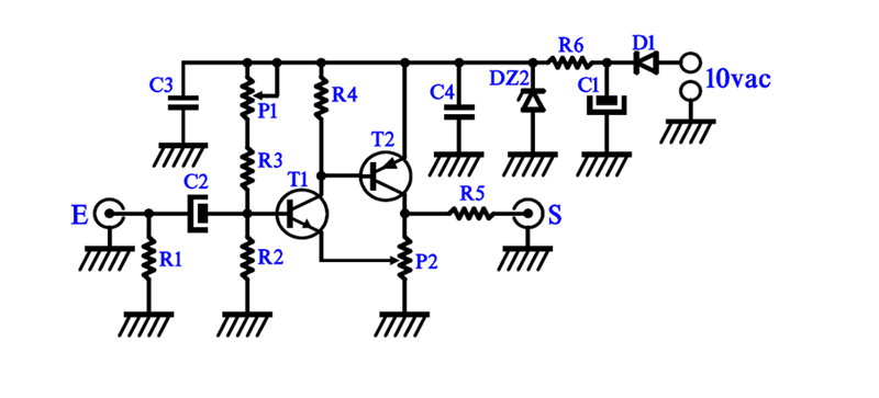 R1 = 150 1/4W R2 = 2200 1/4W R3 = 4700 1/4W R4 = 4700 1/4W R5 = 68 1/4W R6 = 330 1/4W P1 = 22000 lin (A) P2 = 2200 lin (A) C1 = 100 à 220 µF/25V C2 = 100 à 220 µF/25V C3 = 47 à 220 nF/63V C4 = 47 à 220 nF/63V T1 = BC182 T2 = 2N2907A D1 = 1N4003 DZ2 = BZX55C10V E = Entrée (input) S = Sortie (output) P1 = output voltage level (lightness) P2 = gain (contrast) The schematic shown was taken from the French website http://www.cfp-radio.com/. Further details regarding its construction can be found there, by clicking on Realasitations on left, scrolling down to the television section and clicking on “Preamplicicateur video pour anciens teliviseurs monochromes” It can be made as a standalone unit or incorporated into a TV set. A composite input source is connected to the input from freeview box or DVD player etc and the output to the grid of the video amplifier valve, without a capacitor. This circuit has been built by the writer and installed in an HMV F5.After a bit of fiddling with the controls it gave a beautiful clear picture. The gain control was wired to the front panel to act as a contrast control and the lightness pre-set to an appropriate level which was found by trial and error by adjusting the gain (contrast) and the original brightness control which was left intact. A separate mains transformer was used to supply power however depending on the wiring layout of the valve heater circuit it may be possible to derive adequate voltage from that. Though there is a capacitor on the input, it appears that the DC component of the video signal is effectively restored by the amplifier giving black blacks and white whites. The sound is quite simple - an RCA lead is connected to the input of the sound amplifier, usually just before the volume control. It is advisable to connect two RCA leads together in the case of stereo output from the device concerned. |
|
|
Return to top of page · Post #: 2 · Written at 12:24:44 AM on 19 March 2015.
|
|
|
|
Location: Somewhere, USA
Member since 22 October 2013 Member #: 1437 Postcount: 896 |
|
There’s also a perceivable delay when you modulate and demodulate the signal for nothing. |
|
|
Return to top of page · Post #: 3 · Written at 8:28:57 PM on 17 August 2015.
|
|
|
|
Location: Bentleigh East, VIC
Member since 4 January 2012 Member #: 1055 Postcount: 39 |
|
Thanks for posting this, I've been looking for something like this for a while. ‾‾‾‾‾‾‾‾‾‾‾‾‾‾‾‾‾‾‾‾‾‾‾‾‾‾‾‾‾‾‾‾‾‾‾‾‾‾‾‾‾‾‾‾‾‾‾‾‾‾‾‾‾‾‾‾‾‾‾‾‾‾‾‾‾‾‾‾ "What's that big box by the back door? You didn't buy another old TV from eBay did you?" |
|
|
« Back ·
1 ·
Next »
|
|
|
You need to be a member to post comments on this forum.
|
|
Sign In
Vintage Radio and Television is proudly brought to you by an era where things were built with pride and made to last.
DISCLAIMER: Valve radios and televisions contain voltages that can deliver lethal shocks. You should not attempt to work on a valve radio or other electrical appliances unless you know exactly what you are doing and have gained some experience with electronics and working around high voltages. The owner, administrators and staff of Vintage Radio & Television will accept no liability for any damage, injury or loss of life that comes as a result of your use or mis-use of information on this website. Please read our Safety Warning before using this website.
WARNING: Under no circumstances should you ever apply power to a vintage radio, television or other electrical appliance you have acquired without first having it checked and serviced by an experienced person. Also, at no time should any appliance be connected to an electricity supply if the power cord is damaged. If in doubt, do not apply power.
Shintara - Keepin' It Real · VileSilencer - Maintain The Rage