
Vintage Television
Forum home - Go back to Vintage Television
|
Yellow Wire on CRT Socket!
|
|
|
Return to top of page · Post #: 1 · Written at 6:07:08 PM on 20 March 2014.
|
|
|
|
Location: Mildura, VIC
Member since 5 May 2011 Member #: 896 Postcount: 108 |
|
I have got my PYE all up & running now, but can't seem to locate where the yellow wire on the CRT socket connects to I think it maybe the video signal, as I have a raster but no input from the tuner!! |
|
|
Return to top of page · Post #: 2 · Written at 7:36:31 PM on 21 March 2014.
|
|

|
Location: Wauchope, NSW
Member since 1 January 2013 Member #: 1269 Postcount: 576 |
|
I'm pretty sure it's the video wire, though would have to look at some circuit diagrams (and my main computer is dead). Do you have a circuit diagram for the set? |
|
|
Return to top of page · Post #: 3 · Written at 4:24:47 PM on 22 March 2014.
|
|
|
|
Location: Mildura, VIC
Member since 5 May 2011 Member #: 896 Postcount: 108 |
|
I do have the schematic for this, I have tried connecting the wire around the vicinity of the 6BL8 to inject the video signal that way, still nothing! |
|
|
Return to top of page · Post #: 4 · Written at 5:29:47 PM on 22 March 2014.
|
|
|
|
Location: Wauchope, NSW
Member since 1 January 2013 Member #: 1269 Postcount: 576 |
|
Are you able to trace it via the circuit diagram? It should show where it connects to from the socket, if you know which pin it connects to. |
|
|
Return to top of page · Post #: 5 · Written at 6:42:23 AM on 24 March 2014.
|
|
|
|
Location: Mildura, VIC
Member since 5 May 2011 Member #: 896 Postcount: 108 |
|
I did a comparison with my Kriesler P117 and confirmed that the yellow wire definitely is a Contrast wire It goes to the contrast potentiometer |
|
|
Return to top of page · Post #: 6 · Written at 6:43:38 AM on 24 March 2014.
|
|
|
|
Location: Mildura, VIC
Member since 5 May 2011 Member #: 896 Postcount: 108 |
|
I will check resistors next, maybe one has gone open circuit in the video input circuit!!! |
|
|
Return to top of page · Post #: 7 · Written at 9:59:37 PM on 24 March 2014.
|
|
|
|
Location: Ballarat, VIC
Member since 4 January 2011 Member #: 803 Postcount: 456 |
|
The yellow wire on CRT's is usually the cathode connection (video signal). Which end isn't connected? It needs to go to the correct spot, guessing won't work. The signal at the input to the 6BL8 video amp is much to small for the CRT to react to. |
|
|
Return to top of page · Post #: 8 · Written at 5:54:43 AM on 28 March 2014.
|
|
|
|
Location: Mildura, VIC
Member since 5 May 2011 Member #: 896 Postcount: 108 |
|
I get sound and I can time into a modulator all works well!! |
|
|
Return to top of page · Post #: 9 · Written at 6:13:11 PM on 5 April 2014.
|
|
|
|
Location: Ballarat, VIC
Member since 4 January 2011 Member #: 803 Postcount: 456 |
|
I don't have an early Pye TV chassis to check where the wire connects to. |
|
|
Return to top of page · Post #: 10 · Written at 11:26:10 AM on 8 April 2014.
|
|
|
|
Location: Mildura, VIC
Member since 5 May 2011 Member #: 896 Postcount: 108 |
|
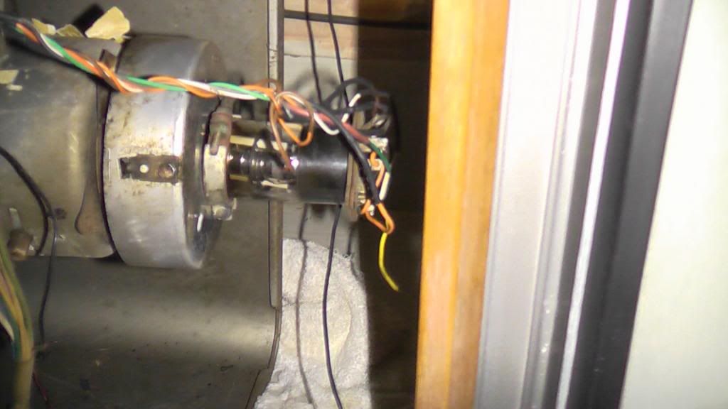
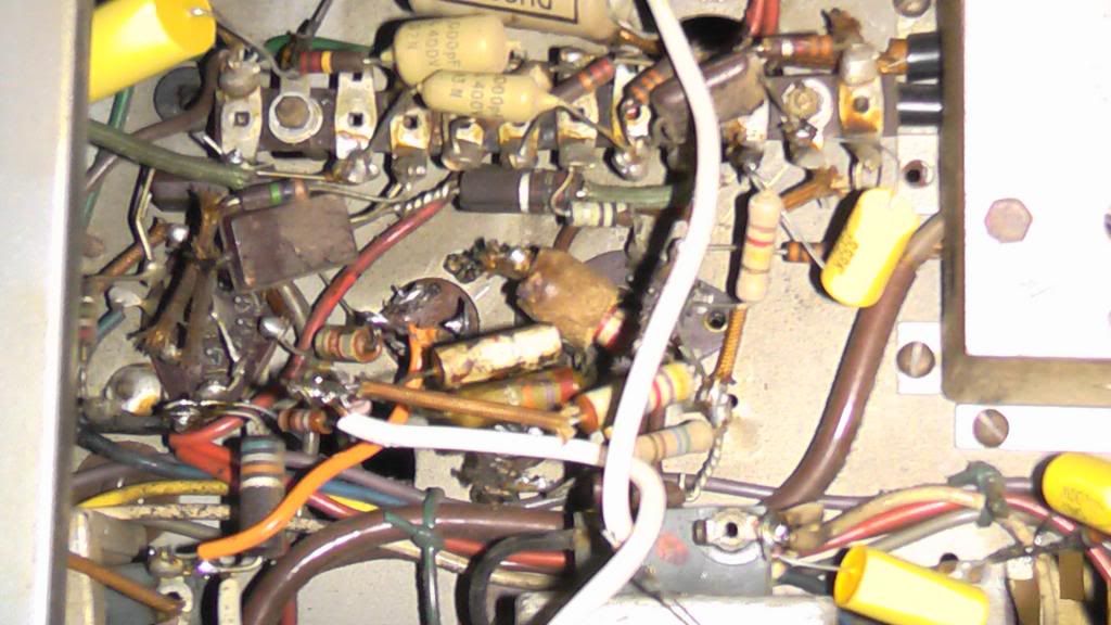
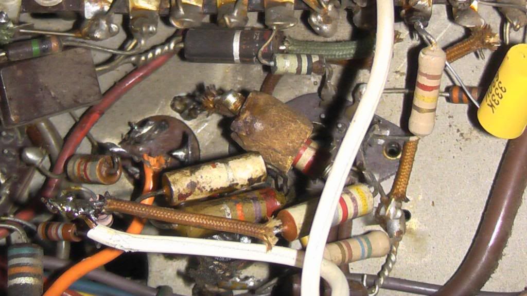
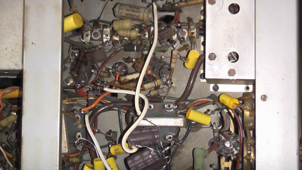
Got some pics: |
|
|
Return to top of page · Post #: 11 · Written at 11:46:23 AM on 8 April 2014.
|
|

|
Administrator
Location: Naremburn, NSW
Member since 15 November 2005 Member #: 1 Postcount: 7643 |
|
The photos are quite tiny. ‾‾‾‾‾‾‾‾‾‾‾‾‾‾‾‾‾‾‾‾‾‾‾‾‾‾‾‾‾‾‾‾‾‾‾‾‾‾‾‾‾‾‾‾‾‾‾‾‾‾‾‾‾‾‾‾‾‾‾‾‾‾‾‾‾‾‾‾ A valve a day keeps the transistor away... |
|
|
Return to top of page · Post #: 12 · Written at 10:00:34 PM on 8 April 2014.
|
|
|
|
Location: Ballarat, VIC
Member since 4 January 2011 Member #: 803 Postcount: 456 |
|
It does help but not as much as I hoped. Things are not quite the same as when your TV left the Marrickville factory! |
|
|
Return to top of page · Post #: 13 · Written at 2:33:29 PM on 9 April 2014.
|
|
|
|
Location: Mildura, VIC
Member since 5 May 2011 Member #: 896 Postcount: 108 |
|
I have posted a video on my YT Channel, |
|
|
Return to top of page · Post #: 14 · Written at 8:10:17 PM on 9 April 2014.
|
|
|
|
Location: Ballarat, VIC
Member since 4 January 2011 Member #: 803 Postcount: 456 |
|
Okay, the video explained some things. |
|
|
Return to top of page · Post #: 15 · Written at 11:41:20 AM on 11 April 2014.
|
|
|
|
Location: Mildura, VIC
Member since 5 May 2011 Member #: 896 Postcount: 108 |
|
More indepth look: |
|
|
You need to be a member to post comments on this forum.
|
|
Sign In
Vintage Radio and Television is proudly brought to you by an era where things were built with pride and made to last.
DISCLAIMER: Valve radios and televisions contain voltages that can deliver lethal shocks. You should not attempt to work on a valve radio or other electrical appliances unless you know exactly what you are doing and have gained some experience with electronics and working around high voltages. The owner, administrators and staff of Vintage Radio & Television will accept no liability for any damage, injury or loss of life that comes as a result of your use or mis-use of information on this website. Please read our Safety Warning before using this website.
WARNING: Under no circumstances should you ever apply power to a vintage radio, television or other electrical appliance you have acquired without first having it checked and serviced by an experienced person. Also, at no time should any appliance be connected to an electricity supply if the power cord is damaged. If in doubt, do not apply power.
Shintara - Keepin' It Real · VileSilencer - Maintain The Rage