Welcome to Australia's only Vintage Radio and Television discussion forums. You are not logged in. Please log in below, apply for an account or retrieve your password.
Australian Vintage Radio Forums
  Home  ·  About Us  ·  Discussion Forums  ·  Glossary  ·  Outside Links  ·  Policies  ·  Services Directory  ·  Safety Warnings  ·  Tutorials

Vintage Television

Forum home - Go back to Vintage Television

 My Kriesler model 79-2 TV
« Back · 1 · Next »
 Return to top of page · Post #: 1 · Written at 5:41:04 PM on 24 February 2014.
Kriesleral's Gravatar
 Location: Mile End, SA
 Member since 23 February 2014
 Member #: 1512
 Postcount: 24

This has been a very long project because it's only with the chassis and tuner removed from the chassis that I have been able to do the necessary re-cap. Also replaced both rectifier valves, and just before the switch-off of analogue, I was able to get a full screen picture, but with horizontal problems and no sound.

I've now tried connecting an older video with RF output on channels 1 and 2 to the TV,but there is no sign of any picture, with or without horizontal rolling.

I suspect that the problem is because this set was built in June, 1959 before the inclusion of channels 0 and 5A, and the frequencies of 0 and 1 on the TV don't correspond with those being put out by the video. Is there anything I can do? I have a modulator which has the same two channels output, so it won't help, and I've used the video on a later Kriesler with perfect results.

Kriesler Magimatic Television


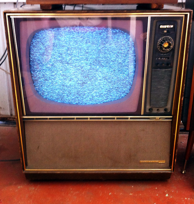
Please help - BTW my electrical knowledge is pretty rudimentary, but this hasn't prevented many previous restorations being successful!

Cheers, Alan.


 Return to top of page · Post #: 2 · Written at 9:04:36 PM on 24 February 2014.
TV Collector's Gravatar
 Location: Ballarat, VIC
 Member since 4 January 2011
 Member #: 803
 Postcount: 456

Do you have snow on the screen with nothing connected to the TV?

The old Ch1 to Ch10 frequency allocations are fairly close to the newer Ch0 to Ch11 ones with the exception of adding Ch 0, 5A and 11 and moving Ch1 up and Ch 4 and 5 down in frequency.

I can understand you having issues with Ch1 but Ch2 has not changed frequency between the two allocations and should work fine. Are you sure the VCR is putting out a signal on Ch 1 and 2?


 Return to top of page · Post #: 3 · Written at 10:14:16 PM on 24 February 2014.
Kriesleral's Gravatar
 Location: Mile End, SA
 Member since 23 February 2014
 Member #: 1512
 Postcount: 24

You're correct, Mr Collector. I meant to say that the video RF outputs to the TV are channel 0 and 1- if it was 2 there'd be no problem.

There is a way to directly inject part of the video signal in a way which by passes the tuner, I believe.


 Return to top of page · Post #: 4 · Written at 9:11:04 PM on 25 February 2014.
TV Collector's Gravatar
 Location: Ballarat, VIC
 Member since 4 January 2011
 Member #: 803
 Postcount: 456

Ahh, there was a picture of the TV running!
Okay, your VCR outputting on Channels 0 and 1 is a problem as the tuner probably won't be able to tune into the "new" Channel 1 as it has been moved a fair bit in frequency.

I wouldn't recommend trying to connect composite video direct to the TV. It is technically possible but there are many complications. You may be better off investing in a stand alone RF modulator. There is a unit selling on Ebay as well as other places that seems to have good results from the feedback I've seen. It puts a signal out on any channel you want. It won't work on the old Channels 0 and 1 though.

Refer to the posts at the end of this thread - http://vintage-radio.com.au/default.asp?f=3&th=540&offset=2


 Return to top of page · Post #: 5 · Written at 9:21:01 PM on 25 February 2014.
Stumatoo's Gravatar
 Location: London, UK
 Member since 23 December 2013
 Member #: 1470
 Postcount: 26

Another way of operating old televisions with no composite video input is to install one. This gives a clear picture and means you don’t need to worry about much of the circuitry in the vintage TV ( ie all the tuning and IF stages) . Unless you are a real purist, I think that is desirable.

For those unclear on this, the signal which used to be received on the antenna consisted of the audio signal and video signal modulated on to the carrier frequencies associated with the particular channel. The first circuits of the set, ie tuner, IF stages and detector are concerned with obtaining a composite video signal; that is just the video information (including of course synchronisation pulses) with no carrier modulation. This is the yellow RCA lead commonly seen along with left and right audio leads on (relatively) modern equipment. This signal is fed to the grid of the video amplifier valve. It is therefore possible to connect such a signal directly to this valve pin.


However a problem arises in that the usual composite signal is, I believe 1 volt peak to peak, which is inadequate to drive the video amplifier valve to a satisfactory level. Also on many sets this will leave no functioning contrast control as contrast is often varied by varying the gain on IF stages, however in yours it looks like contrast is varied by altering screen voltage of the video amp valve, or something like that, starting to challenge the limits of my technical knowledge here!

So the first thing to do is take a yellow RCA lead, cut the plug off one end and connect the wire to the grid of the video amp valve. This is in your set pin 2 of valve 11, and the shield wire to earth
Connecting this to a device with a composite output ( or scart with an adaptor) should give a clear but washed out picture with low contrast.

To reduce the chances of something going bang ( eg your new DVD player!) you might like to connect it through a capacitor( to remove any DC voltages that may, though shouldn’t be present) though these kind of risks seem to be more hype than reality. The capacitor needs to be high value , I tried a 100 μF which was fine.
Its worth bearing in mind that using a capacitor could introduce further issues in that it removes the DC component of the video signal which could potentially upset the voltages in the set. Then again it might not, limits of my technical knowledge again , and it didn’t cause any problem for me once I used a big enough one.


To remedy the lack of contrast it is possible to construct a simple supplementary video amplifier. I found a link to such a circuit (or was directed by another website). It is in French, so do a google translate for some interesting translations!

www.cfp-radio.com

Click on Realasitations on left, scroll down to TV section and its “ Preamplicicateur video pour anciens teliviseurs monochromes”

I built it and after a bit of fiddling with the controls it gave a beautiful clear picture on my HMV-F5. I wired the gain control to the front panel to become a contrast control. I could not get hold of the transistors listed in the circuit, so I used a pair of newer ones which as far as I could work out from my limited semiconductor knowledge were similar. Don’t know what they are though and can’t get at the circuit now until I remove the chassis again, but I see little point in doing anything with it now until I can sort out the deflection yoke problem.

The sound is quite simple – cut out R17 and connect an RCA lead to the side of it that connects to the tone and volume control. This goes into the audio out of the device. I usually take 2 audio leads, one for left and one for right and connect them together for monophonic sound containing both left and right signals.

So I did have a beautiful clear crisp picture and magnificent sound, which the HMV F5 had, but now with the faulty deflection yoke – nothing!


« Back · 1 · Next »
 You need to be a member to post comments on this forum.

Sign In

Username:
Password:
 Keep me logged in.
Do not tick box on a computer with public access.