|
New member Jonk
|
|
|
|
|

|
Location: Annandale, NSW
Member since 14 July 2024
Member #: 2657
Postcount: 19
|
Hi
Thank you for setting up a great resource and community.
I am a radio amateur (VK2JHK) with a soft spot for valve technology but very much an enthusiast not a professional.
I have a small collection of old radios in various states of repair ranging from a Marconi CR100 receiver (works but still a bit rough), an ARC5 T20 aircraft transmitter I am setting up to work on the 40m amateur band to several typical smaller household wireless receivers. Mostly getting these going was replacing valves, obviously dodgy caps and finding damaged IF coils etc but generally not that complicated repairs (although I am proud of the CR100 front panel that was in poor shape that I restored by making a silk screen mask and repainting the markings, turned out pretty nicely).
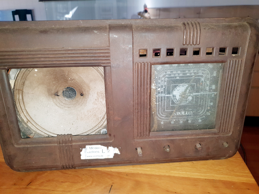
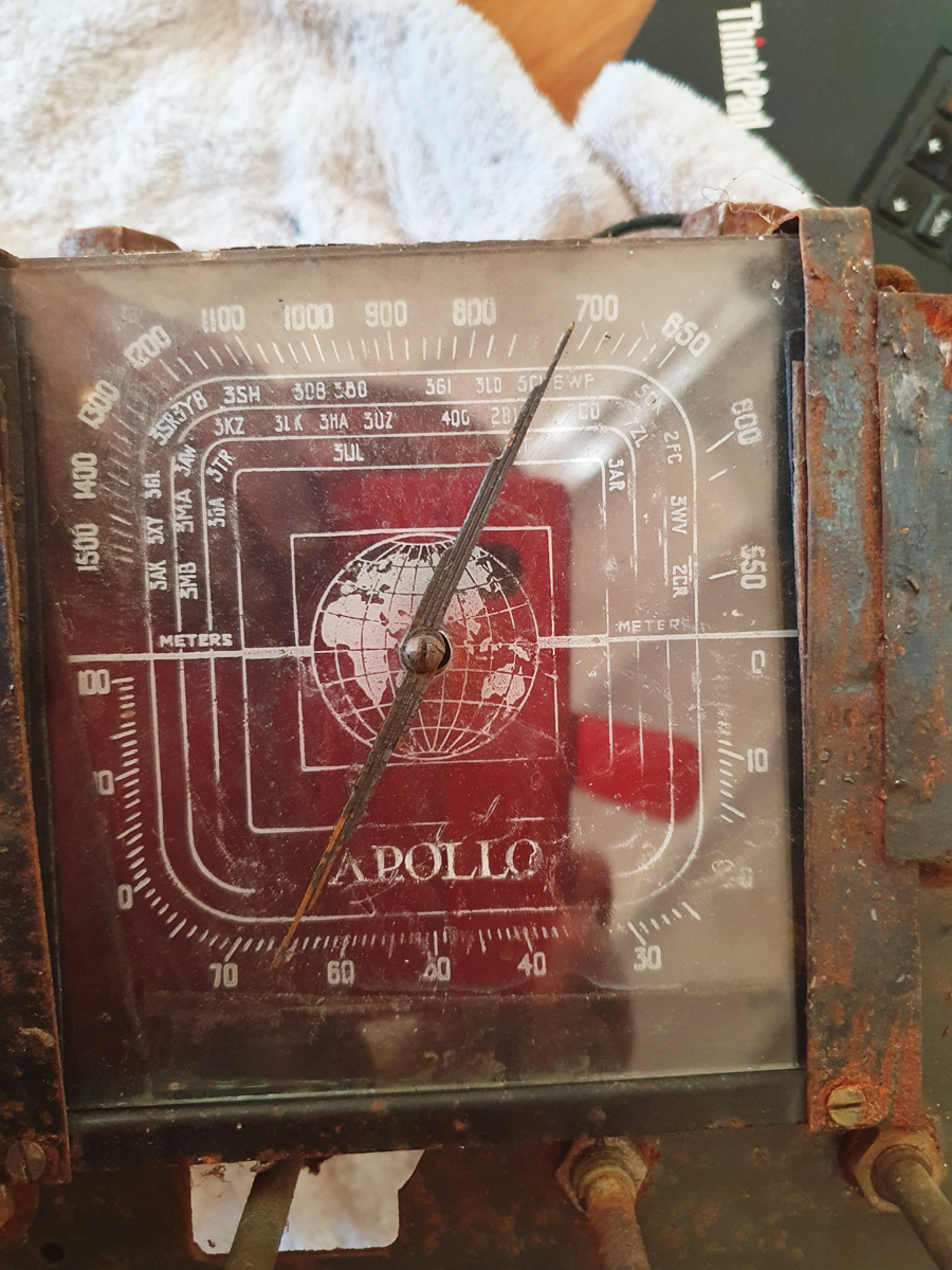
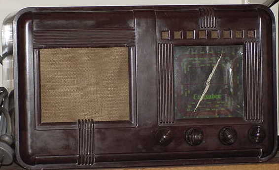
I have just picked up a radio (appears to be 2 band (MW-HF) and the only branding is the word "Apollo" on the dial (overlaid against a map of the world). The MW section is marked with Australian stations. There appears to be the shadow of a licence transfer but very little that I can read from it. I am guessing from looking in the back it is late 30s - 40s?
I haven't pulled out the chassis and had a closer look to see how bad it is but It appears complete although in pretty rough shape. I may have bitten off more than I can chew with it but wanting to see if it can be brought back to life as it has a nice look to it and I am up for a challenge.
I would be grateful if anyone has any information on it.
Jon
|
|
|
|
|

|
Location: Hill Top, NSW
Member since 18 September 2015
Member #: 1801
Postcount: 2256
|
|
|
|
|
|

|
Location: Sydney, NSW
Member since 28 January 2011
Member #: 823
Postcount: 6956
|
Valve line-up will help and some good photos emailed using the Contact Administrator item in the top menu.
And don't be tempted to power it up.
|
|
|
|
|
|
|
Location: Annandale, NSW
Member since 14 July 2024
Member #: 2657
Postcount: 19
|
Thanks for replies, I have pulled out the chassis.
Looks like it is a battery powered mantle radio?
It is fitted with
2 x 1C4
1 x 1C6
1 x 1b5 25s
1 x ?? phillips (rectifier possibly? fitted away from where the RF sections seem to be)
Also what looks like a vibrator (rusted metal cylinder with 6 pin base).
Not what I would think of as a portable radio, too big and heavy - no carry handle - styled like a mantle radio, bakelite case (roughly 16" wide x 10" high x 7.5" deep or approx 400x250x90mm metric).
I will chase up photos. Condition is definitely not in state to power up! 
|
|
|
|
|
|
|
Location: Hill Top, NSW
Member since 18 September 2015
Member #: 1801
Postcount: 2256
|
Ah, pre-octal battery valves.
1C6 - mixer
1C4 - RF amp, IF amp
1B5/25S - dual diodes, AF triode
The unknown one will be the audio output valve. I don't know what would have been used in that situation as your radio is older than the ones I've worked on.
The description of the vibrator sounds right.
See if you can work out the number of the output valve.
Let's see what the photo(s) reveal.
|
|
|
|
|
|
|
Location: Sydney, NSW
Member since 28 January 2011
Member #: 823
Postcount: 6956
|
Not what I would think of as a portable radio, too big and heavy
Sounds like what was called a farm radio.
The line-up 1C6, 2 x IC4, 1B5/25S and 1D4 fits STC chassis type 52B,used in a number of 1936 models.
|
|
|
|
|
|
|
Location: Annandale, NSW
Member since 14 July 2024
Member #: 2657
Postcount: 19
|
Again thanks for the responses.
I have put some photos of the radio on an external web site if people interested.
Hope that is OK to post links - if not feel free to delete. You should be able to click on images to get full size version.
https://www.kellyavia.com/projects/radio/apollo/images/
|
|
|
|
|
|
|
Location: Hill Top, NSW
Member since 18 September 2015
Member #: 1801
Postcount: 2256
|
Thanks for the photos. The site produced a certificate error but I told Firefox to get on with it.
The output valve has 4 pins, so it can't be a 1D4 which has 5 pins.
I'm not familiar with farm radios but I'd imagine you'll have to find or create a suitable power supply for it - once you work out what voltages it wants.
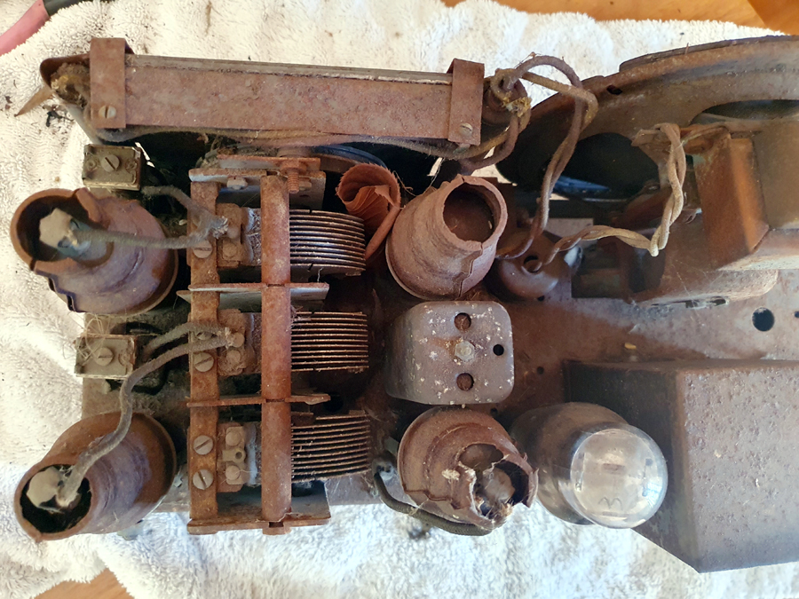
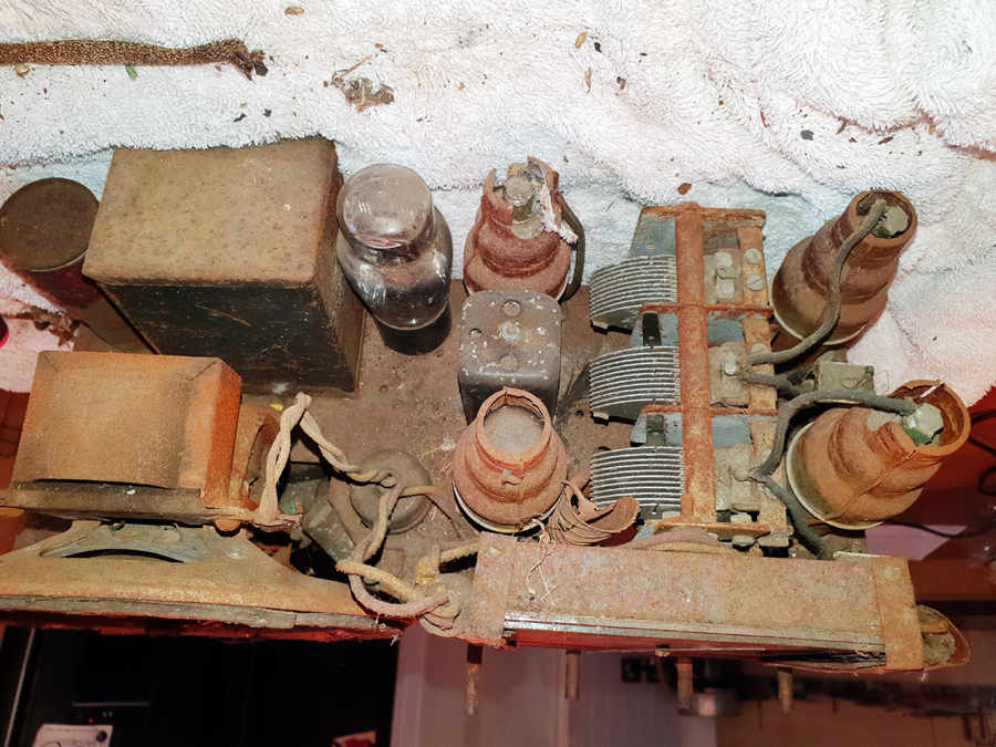
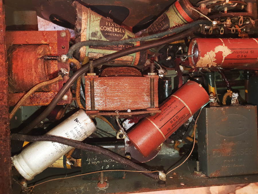
I wouldn't put much faith in those old tubular capacitors or the oil-filled rectangular one. The electros look to be mouse/snail-chewed as well.
Lots of dust, rust and webs to get rid of.
Let's see what the other members have to say.
|
|
|
|
|
|
|
Location: Sydney, NSW
Member since 28 January 2011
Member #: 823
Postcount: 6956
|
The output valve may be a type 30.
Some brand suggestions:
"Oceanic" a house brand of Mick Simmons stores. Model unknown.
https://image.invaluable.com/housePhotos/Lawsons/04/582804/H0669-L90838027.jpg
QUOTE: 1930’s - After tariff protection was introduced by the Commonwealth Government in 1930 the company concentrated on selling Australian made radios. They also advertised “Mick Simmons own receiver, Oceanic” at a lower price than the equivalent AWA and Airzone radios of the period.
The manufacturer of Oceanic Brand radios was probably the Zenith Radio Co. Ltd.
The Zenith Radio Co. Ltd. manufactured generic radios for a variety of resellers, department stores, etc. who branded the radios with their own brand. The company was not associated with the Zenith Radio Corp. of America.
Also Eclipse Croyden (1938) Model not specified:
http://avrs.org.au/Images/2012-06-23AR.jpg
Also Crusader (NZ). I note that some of those Ducon capacitors mention NZ:
http://www.grayj.id.au/all_site_images/crusader.jpg
QUOTE: Crusader was a brand sold by Bond and Bond. Early models (1930's) appear to be manufactured by Radio Ltd, later models (1940's) appear to be Collier & Beale.
The sticker on the set mentions Old Modern Auctions which is at 2 Mornington-Tyabb Rd, Tyabb VIC
That set is in very rough condition. Not one I'd take on unless it had sentimental value to someone, and even then I'd need persuading. Definitely not my idea of a first resto candidate!
|
|
|
|
|

|
Location: Toongabbie, NSW
Member since 19 November 2015
Member #: 1828
Postcount: 1409
|
Guys that's the sort of thing I love to restore!
Its a rusted 'basket case'.
My ramble thoughts.
The only good news about it is that its nearly all there.
That poor thing needs a complete dismantle, refurbish each part and re-assemble.
Months of fun for all the family!
The rust top side precludes just blowing down and powering up.
I downloaded photos with no problem good photography.
This is a very time consuming business to take photos (done) draw a wiring diagram, then remove each part one by one until you have a bare chassis and about 200 individual parts,
Next you refurbish each part and test ok.
Then re-assemble just like in the factory building new ones.
A lot of the caps will need replacing or hiding a new one in the old cases if the vintage look must be retained.
Most resistors could be ok.
Coils probably ok.
Valve ditto.
Speaker may be a bolt up type that can be easily stripped and fettled.
Chassis stripped back to bare metal and refinished.
So on and so on.
Needs an experienced restorer to do this or a first timer going very slowly and learning on the job.
If it was for my Granny I would do it otherwise no!
Fred.
|
|
|
|
|
|
|
Location: Annandale, NSW
Member since 14 July 2024
Member #: 2657
Postcount: 19
|
Wow! thank you folks for the responses, I am impressed by the knowledge of people here, I have been looking for days for similar examples on the web but drawing blanks but the links to photos by GTC are pretty much the same radio as I picked up.
I appreciate people's input about the difficulty of restroring this radio - my personal concerns are twofold:
1. getting a circuit diagram of the radio - unless I create one from the radio itself. I would not start without one. Given the info in the posts above I may have a better chance of finding a diagram (or at least something in the ballpark I can use as a basis for tracing out the radio as it is).
2. is the radio of any historical value? - if it is not particularly valuable I would feel much happier about working on it.
I enjoy a challenge - it is not a radio with any personal value other than I saw it in a country junk shop on the weekend and kind of liked the look of it and the owner accepted my lowball offer - plus it seemed all intact, if not exactly pristine
Similar to Fred's suggestions, my initial thought was to strip it down completely to bare chassis (obviously dependent on either getting a diagram for it or on how well I can create a circuit diagram) and then rebuild it replacing things like the caps with modern ones dressed to look like the originals etc.
The variable capacitor looks tricky though - not sure how easy this would be to refurbish (or how easy to source one that would fit and be in better condition). I haven't really tried freeing it up yet but it looks pretty cruddy.
I am not so much worried about the scale of the job or the time, I am not in a hurry and have several other projects on the go as well so happy to potter a bit with it and take my time.
However if the radio is something valuable I would hesitate in stripping it down as I don't want to butcher something important.
It didn't cost me much so if it is feasible I am pretty happy to have a go and realise it will be a slow and potentially can of worms project.
Again thank you to all who have responded, I appreciate the input (and welcome any more input) and am very impressed by the knowledge here.
Jon
|
|
|
|
|

|
Location: NSW
Member since 10 June 2010
Member #: 681
Postcount: 1408
|
Here is a recent discussion on cleaning variable capacitors. Opinions vary as you will see. All are valid depending on your circumstances:
https://vintage-radio.com.au/default.asp?f=2&th=1335#15088
There have been cases of people dropping the whole wiring harness out of the radio in order to refurbish the chassis. This will mean dropping out the valve bases and other components as well as necessary or possible. Lots of photographs needed. Mind you I haven't tried this myself - others may gave comments.
Dropping the wiring harness I imagine would minimise errors in recreating the circuitry in a chassis stripped for restoration.
But it might be best to get it going first in case there is any unobtainium component stopping it from working.You could perhaps clean it up as best you can, then checking it over generally for obvious faults then get it going by repacing paper caps and dud electrolytics, then try it with a dim bulb set up. (Dim bulb set up is a say 60 watt 240V bulb in series with the radio in the active line - this limits current if there is a fault like a short circuit - could save the mains transformer).
Once you know it works then drop out the circuitry and clean up the chassis.
|
|
|
|
|
|
|
Location: Toongabbie, NSW
Member since 19 November 2015
Member #: 1828
Postcount: 1409
|
Hi Jon, for a bit of inspiration trawl through the index in the 'special projects' section and find the resto I did on a Kriesler 3K15 set.
I stripped the chassis bare, refurbished a lot of parts, and re-built the set using a lot of different techniques as I went.
I have no training in 'radio' and 20 years ago knew very little about vintage stuff.
You will note I have made up for time lost!
That Kriesler was not quite as bad as your set but similar in that its a back to bare metal resto.
It would be great to see someone else do some articles for the special projects section.
Its easy, just do the job, make notes as you go and put in down in a file with pictures of what happened.
Also have a look for the ''Yakandandra' re-build very early on.
That one was found in a field and did have rust holes in the chassis!
I took the rusty wreck , made it work again and built up a cabinet for it to live in.
Cheers, Fred.
|
|
|
|
|
|
|
Location: Hill Top, NSW
Member since 18 September 2015
Member #: 1801
Postcount: 2256
|
For an unknown radio I will make a drawing of the underside of the chassis, mark the positions of the valve sockets, tag strips, and other major components and then add the various capacitors and resistors with their values. Also of course not forgetting the various wires.
From that, I will then draw a conventional-looking schematic. After that comes the checking, to make sure that what you've ended up with makes sense from a theoretical standpoint.
However in my opinion you've picked one of the worst radio jobs to do, because it uses rare valves (one of which is unknown) condition unknown, it's a rustheap requiring a lot of manual labour to clean. There's a vibrator power supply, again condition unknown, and the vibrator could be worn out. The first photo shows the battery leads, with bare wires showing. The needed voltage of the batteries is unknown.
In battery radios the valve filaments form resistive networks so if the wrong voltage is present it could burn out a filament destroying the valve, and also send the rest of the voltages haywire. They are a trap for the unwary.
Personally, since I'm more of a valve collector these days, I'd keep the valves and dump the rest. But the other members would probably scream at me for that. I also would have no idea if your set has any rarity value, even given the fact that none of us has heard of this radio before.
Anyway, if you do go ahead, make the drawing of what parts are where, so that when you change them out you won't forget where you're up to.
Also, check inside the metal box that's next to the vibrator. I'd expect it will have the high-voltage parts that work with the vibrator.
|
|
|
|
|
|
|
Location: Sydney, NSW
Member since 28 January 2011
Member #: 823
Postcount: 6956
|
1. getting a circuit diagram of the radio - unless I create one from the radio itself. I would not start without one. Given the info in the posts above I may have a better chance of finding a diagram (or at least something in the ballpark I can use as a basis for tracing out the radio as it is).
There may be one somewhere, but I could find no schematic for that radio in the usual places given the various brand names shown or using the valve line-up. It strikes me as being a generic set manufactured by one of the companies known to provide them to others for 'house branding' such as Oceanic.
2. is the radio of any historical value? - if it is not particularly valuable I would feel much happier about working on it.
IMO it has zero historical or other value. At HRSA auctions in Sydney in my experience there are two categories of sets that attract little or no interest: consoles and battery sets, regardless of condition.
Frankly, if you want to restore a valve radio, I'd suggest starting with a model that is well known and in better condition.
|
|
|
|
|
|
You need to be a member to post comments on this forum.
|
