
Member Introductions
Forum home - Go back to Member Introductions
|
Greetings from Maitland (Newcastle) NSW
|
|
|
« Back ·
1 ·
Next »
|
|
|
Return to top of page · Post #: 1 · Written at 9:39:41 AM on 16 May 2014.
|
|
|
|
Location: Maitland, NSW
Member since 16 May 2014 Member #: 1574 Postcount: 19 |
|
Hiya, |
|
|
Return to top of page · Post #: 2 · Written at 10:41:52 AM on 16 May 2014.
|
|

|
Location: Melbourne, VIC
Member since 20 September 2011 Member #: 1009 Postcount: 1263 |
|
Welcome to the Forum. 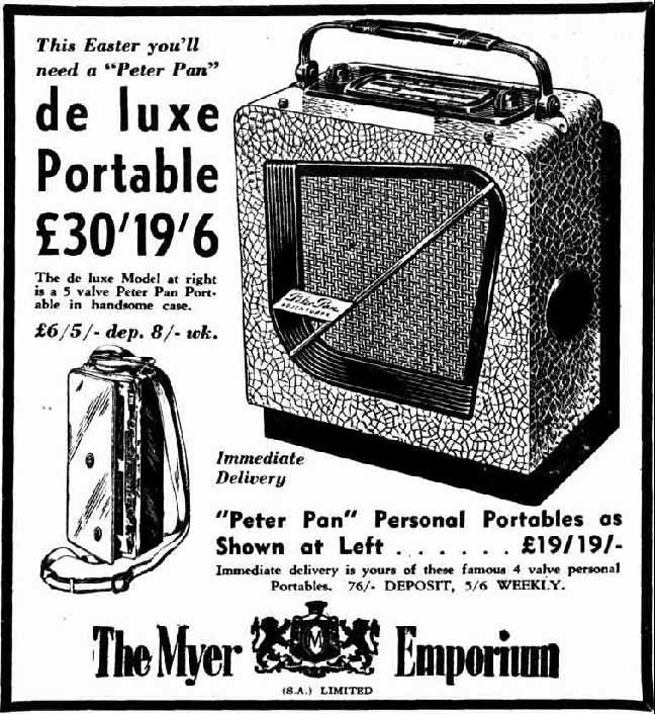 Both Astor & Peter Pan radios will have a 2 or 3 letter model prefix stamped somewhere on the chassis. EDIT: The Peter Pan "CKP" is, circuit wise, an improved version of the Astor "KP" from late 1946. |
|
|
Return to top of page · Post #: 3 · Written at 11:26:11 PM on 16 May 2014.
|
|
|
|
Location: Melbourne, VIC
Member since 20 September 2011 Member #: 1009 Postcount: 1263 |
|
The Peter Pan CKP & Astor PR are both battery sets. They both use 2 X 45 volt "B" batteries for the HT & a 1.5 volt "A" for the valve filaments. "A" & "B" batteries have not been available for many years. The radios can be made to work by stringing together 10 X 9 volt batteries in series for the HT & some D cells in parallel for the filaments. Someone a while ago was making a step-up device that could deliver the HT voltage from just a couple of AA batteries.There also was a unit made by Astor to run the Peter Pan CKP on mains power. |
|
|
Return to top of page · Post #: 4 · Written at 9:04:27 PM on 17 May 2014.
|
|

|
Administrator
Location: Naremburn, NSW
Member since 15 November 2005 Member #: 1 Postcount: 7633 |
|
G'day OldNerd, ‾‾‾‾‾‾‾‾‾‾‾‾‾‾‾‾‾‾‾‾‾‾‾‾‾‾‾‾‾‾‾‾‾‾‾‾‾‾‾‾‾‾‾‾‾‾‾‾‾‾‾‾‾‾‾‾‾‾‾‾‾‾‾‾‾‾‾‾ A valve a day keeps the transistor away... |
|
|
Return to top of page · Post #: 5 · Written at 9:29:14 PM on 20 May 2014.
|
|
|
|
Location: Maitland, NSW
Member since 16 May 2014 Member #: 1574 Postcount: 19 |
|
Thanks for those Schematics (and words of encouragment). |
|
|
Return to top of page · Post #: 6 · Written at 10:01:28 AM on 21 May 2014.
|
|
|
|
Location: Cameron Park, NSW
Member since 5 November 2010 Member #: 770 Postcount: 427 |
|
Think milliamps rather than amps for these battery sets. |
|
|
Return to top of page · Post #: 7 · Written at 3:52:22 PM on 23 May 2014.
|
|
|
|
Location: Maitland, NSW
Member since 16 May 2014 Member #: 1574 Postcount: 19 |
|
Thanks Harold. |
|
|
« Back ·
1 ·
Next »
|
|
|
You need to be a member to post comments on this forum.
|
|
 12mA = Not very big at all.....
Sign In
Vintage Radio and Television is proudly brought to you by an era where things were built with pride and made to last.
DISCLAIMER: Valve radios and televisions contain voltages that can deliver lethal shocks. You should not attempt to work on a valve radio or other electrical appliances unless you know exactly what you are doing and have gained some experience with electronics and working around high voltages. The owner, administrators and staff of Vintage Radio & Television will accept no liability for any damage, injury or loss of life that comes as a result of your use or mis-use of information on this website. Please read our Safety Warning before using this website.
WARNING: Under no circumstances should you ever apply power to a vintage radio, television or other electrical appliance you have acquired without first having it checked and serviced by an experienced person. Also, at no time should any appliance be connected to an electricity supply if the power cord is damaged. If in doubt, do not apply power.
Shintara - Keepin' It Real · VileSilencer - Maintain The Rage