
Member Introductions
Forum home - Go back to Member Introductions
|
New member Jonk
|
|
|
Return to top of page · Post #: 31 · Written at 6:54:54 PM on 29 July 2024.
|
|
|
|
Location: Belrose, NSW
Member since 31 December 2015 Member #: 1844 Postcount: 2712 |
|
Your circuit looks pretty close, no obvious errors on a quick peer review! |
|
|
Return to top of page · Post #: 32 · Written at 11:19:46 PM on 29 July 2024.
|
|

|
Location: Hill Top, NSW
Member since 18 September 2015 Member #: 1801 Postcount: 2256 |
|
I see a few questionable things there, but then again my specialty is AC sets rather than battery ones. Still, I'll list what doesn't seem right to me. |
|
|
Return to top of page · Post #: 33 · Written at 11:37:29 AM on 31 July 2024.
|
|
|
|
Location: Annandale, NSW
Member since 14 July 2024 Member #: 2657 Postcount: 19 |
|
Thanks Robbbert and Ian, much appreciated. I will let you know what I find when I recheck the radio in a day or two. |
|
|
Return to top of page · Post #: 34 · Written at 11:39:19 AM on 3 August 2024.
|
|
|
|
Location: Annandale, NSW
Member since 14 July 2024 Member #: 2657 Postcount: 19 |
|
Thanking you 2 for your input, it has helped greatly.
You are right, I missed that, inside the can that covers the transformer there are 2 capacitors, one from each of the secondaries to earth, they are pretty bad (splitting apart and gooey)
Yep you are right, I had R5 wrong, it does exactly what you surmised, it doesn't connect to the cathode, it runs to the G2 pin of the 1C4 and pin 5 (G3,G5) of the 1C6
I had that wrong as well, the choke comes from the battery and is then connected to the transformer primary centre tap (and that line is connected to earth via C5 after the choke).
I checked and re-checked the connections on the 1B5 multiple times and kept coming up with the same answer (over 2 days)... I started in desperation to think perhaps the valve wasn't using the triode part at all. Then after removing some of the components to make really sure there wasn't something hiding there I hadn't seen, I saw the marking on the valve socket and I realised I had misidentified pin1  All the connections were 1 pin out! What a goose I am! :-x I have redrawn the circuit fixing the bits above up. https://www.kellyavia.com/projects/radio/apollo/images/pdf/197.pdf I really appreciate the input on this. |
|
|
Return to top of page · Post #: 35 · Written at 6:49:43 PM on 3 August 2024.
|
|

|
Location: Melbourne, VIC
Member since 20 September 2011 Member #: 1009 Postcount: 1263 |
|
I’ve come in late to this discussion. |
|
|
Return to top of page · Post #: 36 · Written at 10:58:37 PM on 3 August 2024.
|
|
|
|
Location: Hill Top, NSW
Member since 18 September 2015 Member #: 1801 Postcount: 2256 |
|
Had a look at the new diagram and things look much better. The only issue now is around the 1C6 frequency changer tube. |
|
|
Return to top of page · Post #: 37 · Written at 9:40:22 AM on 4 August 2024.
|
|
|
|
Location: Belrose, NSW
Member since 31 December 2015 Member #: 1844 Postcount: 2712 |
|
Yes, V2 pin 6 is a worry. |
|
|
Return to top of page · Post #: 38 · Written at 10:38:00 AM on 4 August 2024.
|
|
|
|
Location: Belrose, NSW
Member since 31 December 2015 Member #: 1844 Postcount: 2712 |
|
Oh, on your circuit, there is a note about a suspected two-part electro,, with 3 pins. |
|
|
Return to top of page · Post #: 39 · Written at 4:00:37 PM on 5 August 2024.
|
|
|
|
Location: Annandale, NSW
Member since 14 July 2024 Member #: 2657 Postcount: 19 |
Yep, as you both suspected, I had connected that wrongly on the schematic. on checking, V2 pin 6 goes to V4 pin 1 as Ian suggested. I have redrawn the diagram. https://www.kellyavia.com/projects/radio/apollo/images/pdf/197.pdf
I think you could well be right. Pity I can't find a schematic for the 552/12  Again, thanking all for their input, it is really helpful, interesting and much appreciated.  cheers Jon |
|
|
Return to top of page · Post #: 40 · Written at 5:56:04 PM on 5 August 2024.
|
|
|
|
Location: Hill Top, NSW
Member since 18 September 2015 Member #: 1801 Postcount: 2256 |
|
OK that's sorted out the filament. |
|
|
Return to top of page · Post #: 41 · Written at 7:13:04 PM on 5 August 2024.
|
|
|
|
Location: Belrose, NSW
Member since 31 December 2015 Member #: 1844 Postcount: 2712 |
|
I've often wondered how these 6V farm radios were powered, or, more particularly, how the 6V lead-acid battery was charged. |
|
|
Return to top of page · Post #: 42 · Written at 12:34:03 PM on 8 August 2024.
|
|
|
|
Location: Annandale, NSW
Member since 14 July 2024 Member #: 2657 Postcount: 19 |
yep you are right, I missed a resistor (R.5 in my notation) that connects that to the HT line I have redrawn the diagram again. https://www.kellyavia.com/projects/radio/apollo/images/pdf/197.pdf Hopefully this getting closer! Really appreciate the input. Also assume it is OK to keep posting on this "introduction" thread? Or should I start a new one in another category?
I lived on a property north of Bourke for a while in the 80s/early 90s, one of the neighbouring homesteads had a windmill electrical generator that had been used for powering lights in the homestead (Windlite?). The homestead had burnt down several years before I lived there but the windmill remained, now unused. It was a specialised mill designed as a generator rather than a converted pumping windmill. Prior to getting power most of the properties in the area ran a big old single cylinder petrol generator that charged a bank of glass wet cell batteries that supplied 32V to the homestead. |
|
|
Return to top of page · Post #: 43 · Written at 2:09:05 PM on 8 August 2024.
|
|
|
|
Location: Hill Top, NSW
Member since 18 September 2015 Member #: 1801 Postcount: 2256 |
|
Right, you've done a general tidy-up as well. |
|
|
Return to top of page · Post #: 44 · Written at 9:35:57 AM on 9 August 2024.
|
|
|
|
Location: Melbourne, VIC
Member since 20 September 2011 Member #: 1009 Postcount: 1263 |
|
I found a schematic for the Croyden/Eclipse 552 Series. 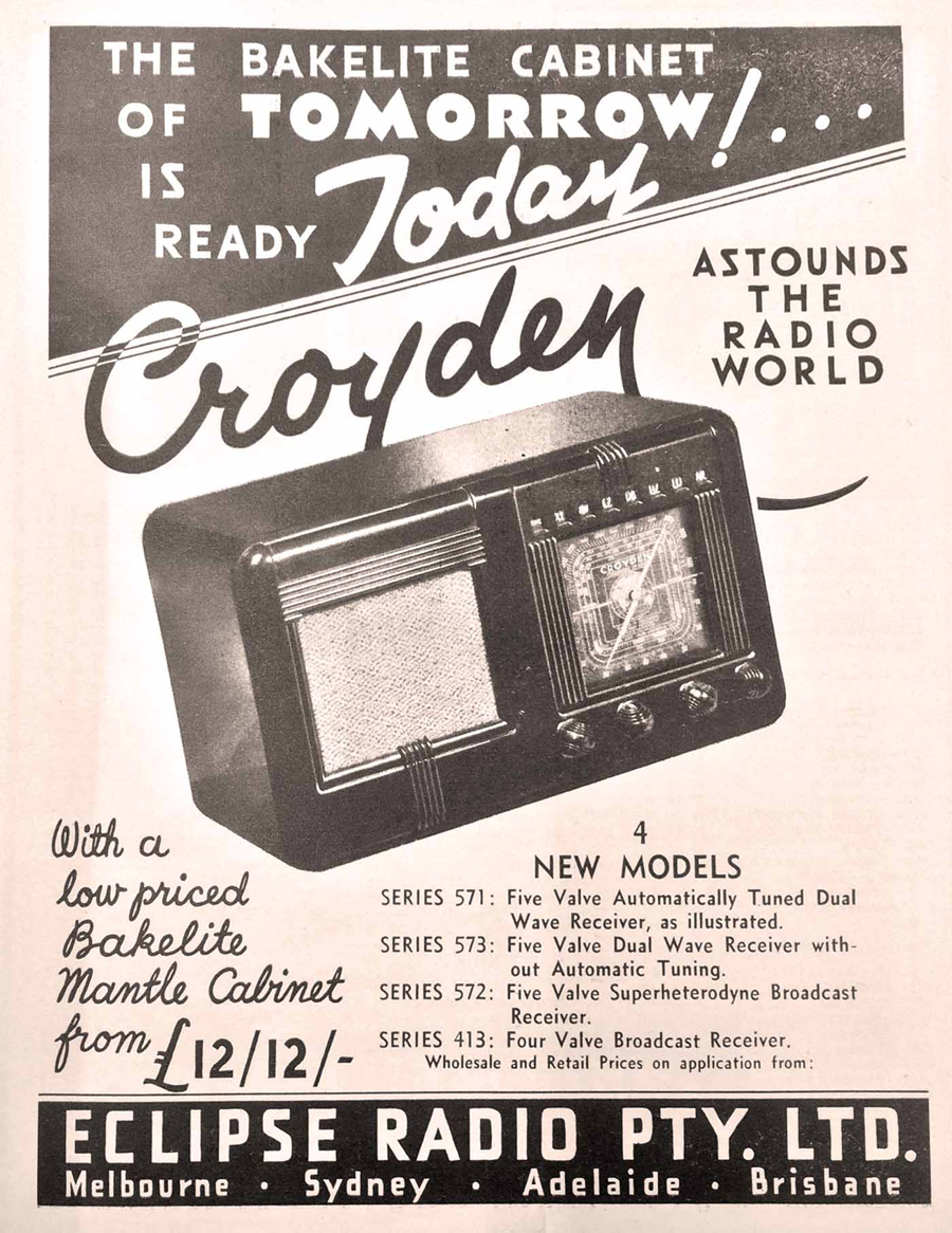 Above is an trade advertisement from a 1937 Radio Retailer of Australia. The models shown are AC only. |
|
|
Return to top of page · Post #: 45 · Written at 5:31:47 PM on 9 August 2024.
|
|
|
|
Location: Annandale, NSW
Member since 14 July 2024 Member #: 2657 Postcount: 19 |
|
I would be keen to have a look however does Kevin still supply the DVD? I would not want to circumvent work he has done, if he still sells the disk. |
|
|
You need to be a member to post comments on this forum.
|
|
Sign In
Vintage Radio and Television is proudly brought to you by an era where things were built with pride and made to last.
DISCLAIMER: Valve radios and televisions contain voltages that can deliver lethal shocks. You should not attempt to work on a valve radio or other electrical appliances unless you know exactly what you are doing and have gained some experience with electronics and working around high voltages. The owner, administrators and staff of Vintage Radio & Television will accept no liability for any damage, injury or loss of life that comes as a result of your use or mis-use of information on this website. Please read our Safety Warning before using this website.
WARNING: Under no circumstances should you ever apply power to a vintage radio, television or other electrical appliance you have acquired without first having it checked and serviced by an experienced person. Also, at no time should any appliance be connected to an electricity supply if the power cord is damaged. If in doubt, do not apply power.
Shintara - Keepin' It Real · VileSilencer - Maintain The Rage