
Wanted and For Sale
Forum home - Go back to Wanted and for sale
|
Vanguard 'Sealed Radio' info wanted
|
|
|
« Back ·
1 ·
Next »
|
|
|
Return to top of page · Post #: 1 · Written at 4:56:28 PM on 4 March 2017.
|
|

|
Location: Western Victoria, VIC
Member since 14 November 2009 Member #: 579 Postcount: 110 |
|
I recently found an early 30's Vanguard 'sealed radio', made by Stokoe Motors Pty Ltd (Trove shows an add for the manufacturer at 559 Elizabeth Street, Melbourne). Some adds state that the Vanguard uses Loftin White amplification. Stokoe Motors appear to be an early manufacturer of car radios, and I wonder if the 'sealed radio' slogan was a part of their car radio advertising (e.g. sealed to limit interference)? I haven't been able to find a picture in any of the collector books, or online, so guessing it's probably uncommon? Does anyone know anything about this model, or chassis, and have a circuit? It is serial number 1001 - possibly the first one? Also, does anyone know where speaker cone material can be purchased?? I think it will be a good winter project. 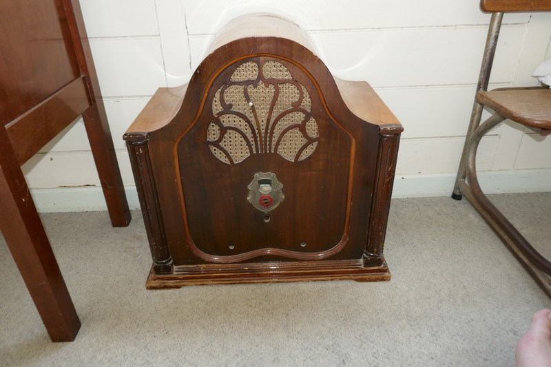 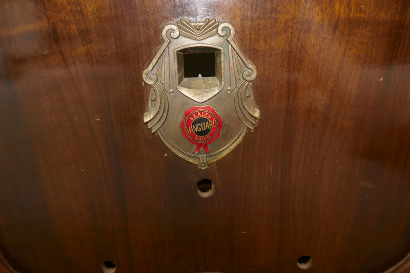 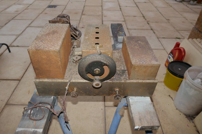 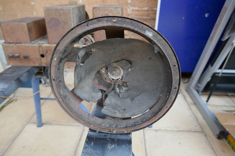 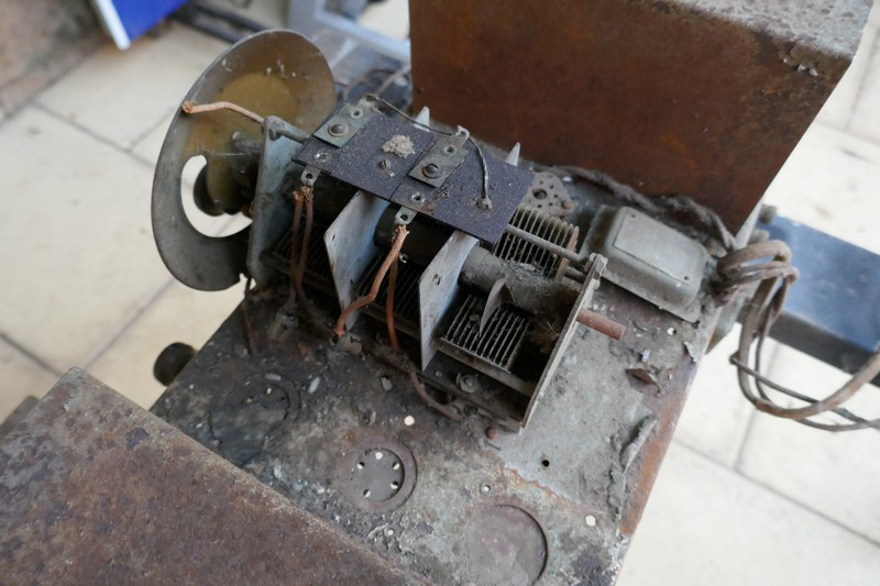 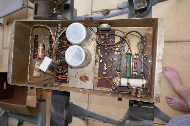 ‾‾‾‾‾‾‾‾‾‾‾‾‾‾‾‾‾‾‾‾‾‾‾‾‾‾‾‾‾‾‾‾‾‾‾‾‾‾‾‾‾‾‾‾‾‾‾‾‾‾‾‾‾‾‾‾‾‾‾‾‾‾‾‾‾‾‾‾ Robert |
|
|
Return to top of page · Post #: 2 · Written at 6:23:19 PM on 4 March 2017.
|
|

|
Administrator
Location: Naremburn, NSW
Member since 15 November 2005 Member #: 1 Postcount: 7634 |
|
'Sealed Set' may be some sort of marketing tool or slogan. It's definitely not a sealed set in the true sense of the phrase - for which the original owner would have been thankful. ‾‾‾‾‾‾‾‾‾‾‾‾‾‾‾‾‾‾‾‾‾‾‾‾‾‾‾‾‾‾‾‾‾‾‾‾‾‾‾‾‾‾‾‾‾‾‾‾‾‾‾‾‾‾‾‾‾‾‾‾‾‾‾‾‾‾‾‾ A valve a day keeps the transistor away... |
|
|
Return to top of page · Post #: 3 · Written at 9:10:09 PM on 4 March 2017.
|
|

|
Location: Wangaratta, VIC
Member since 21 February 2009 Member #: 438 Postcount: 5724 |
|
Looks like it may need reverse engineering: Sealed against dust I would believe. |
|
|
Return to top of page · Post #: 4 · Written at 12:06:29 AM on 5 March 2017.
|
|
|
|
Location: Western Victoria, VIC
Member since 14 November 2009 Member #: 579 Postcount: 110 |
|
Hi Marcc, ‾‾‾‾‾‾‾‾‾‾‾‾‾‾‾‾‾‾‾‾‾‾‾‾‾‾‾‾‾‾‾‾‾‾‾‾‾‾‾‾‾‾‾‾‾‾‾‾‾‾‾‾‾‾‾‾‾‾‾‾‾‾‾‾‾‾‾‾ Robert |
|
|
Return to top of page · Post #: 5 · Written at 2:01:35 PM on 5 March 2017.
|
|
|
|
Location: Wangaratta, VIC
Member since 21 February 2009 Member #: 438 Postcount: 5724 |
|
I am wondering if you got the count right. I see in the pan photo sockets for 5 & an out of place Octal socket mounted on one. |
|
|
Return to top of page · Post #: 6 · Written at 2:48:13 PM on 5 March 2017.
|
|
|
|
Location: Western Victoria, VIC
Member since 14 November 2009 Member #: 579 Postcount: 110 |
|
Hi Marrc, ‾‾‾‾‾‾‾‾‾‾‾‾‾‾‾‾‾‾‾‾‾‾‾‾‾‾‾‾‾‾‾‾‾‾‾‾‾‾‾‾‾‾‾‾‾‾‾‾‾‾‾‾‾‾‾‾‾‾‾‾‾‾‾‾‾‾‾‾ Robert |
|
|
Return to top of page · Post #: 7 · Written at 10:56:25 AM on 7 March 2017.
|
|

|
Location: Perth, WA
Member since 19 November 2008 Member #: 381 Postcount: 240 |
|
There are many advertisements for Vanguard radios in 1931 in TROVE. 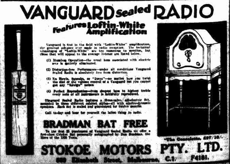 |
|
|
« Back ·
1 ·
Next »
|
|
|
You need to be a member to post comments on this forum.
|
|

Sign In
Vintage Radio and Television is proudly brought to you by an era where things were built with pride and made to last.
DISCLAIMER: Valve radios and televisions contain voltages that can deliver lethal shocks. You should not attempt to work on a valve radio or other electrical appliances unless you know exactly what you are doing and have gained some experience with electronics and working around high voltages. The owner, administrators and staff of Vintage Radio & Television will accept no liability for any damage, injury or loss of life that comes as a result of your use or mis-use of information on this website. Please read our Safety Warning before using this website.
WARNING: Under no circumstances should you ever apply power to a vintage radio, television or other electrical appliance you have acquired without first having it checked and serviced by an experienced person. Also, at no time should any appliance be connected to an electricity supply if the power cord is damaged. If in doubt, do not apply power.
Shintara - Keepin' It Real · VileSilencer - Maintain The Rage