
Wanted and For Sale
Forum home - Go back to Wanted and for sale
|
Old Radio
|
|
|
Return to top of page · Post #: 1 · Written at 3:59:08 AM on 5 March 2014.
|
|
|
|
Location: Perth, WA
Member since 7 May 2012 Member #: 1140 Postcount: 157 |
|
I have a Lewbury Lectric radio that has seen better days I have to try and restore for a lovely lady. Upon seeing it I said no but she begged me to have a go. |
|
|
Return to top of page · Post #: 2 · Written at 10:14:37 AM on 5 March 2014.
|
|

|
Location: Wangaratta, VIC
Member since 21 February 2009 Member #: 438 Postcount: 5720 |
|
80 rectifier; 59 output; 57 (6J7). Are they all of the valves? If it's a screen grid (autodyne) I think we need a couple of 57's. |
|
|
Return to top of page · Post #: 3 · Written at 11:40:58 AM on 5 March 2014.
|
|

|
Location: Sydney, NSW
Member since 28 January 2011 Member #: 823 Postcount: 6956 |
|
If it's of any assistance, we discussed Lewbury Lectric last year here: |
|
|
Return to top of page · Post #: 4 · Written at 8:06:33 PM on 5 March 2014.
|
|
|
|
Location: Perth, WA
Member since 7 May 2012 Member #: 1140 Postcount: 157 |
|
Hello Marc, |
|
|
Return to top of page · Post #: 5 · Written at 9:31:27 PM on 5 March 2014.
|
|
|
|
Location: Wangaratta, VIC
Member since 21 February 2009 Member #: 438 Postcount: 5720 |
|
OK! TRF most likely. Need to see what coils it has. I have seen sets like this. Astor GN (Football was one) Cult following horror set otherwise. It did have detector diodes in the tube. |
|
|
Return to top of page · Post #: 6 · Written at 7:16:16 AM on 6 March 2014.
|
|

|
Location: Melbourne, VIC
Member since 20 September 2011 Member #: 1009 Postcount: 1263 |
|
Here are a couple of typical early 1930's 3 valve radio circuits. These ones use valve types 57, 2A5 (2.5 volt version of a 42 & 6F6) and 80. 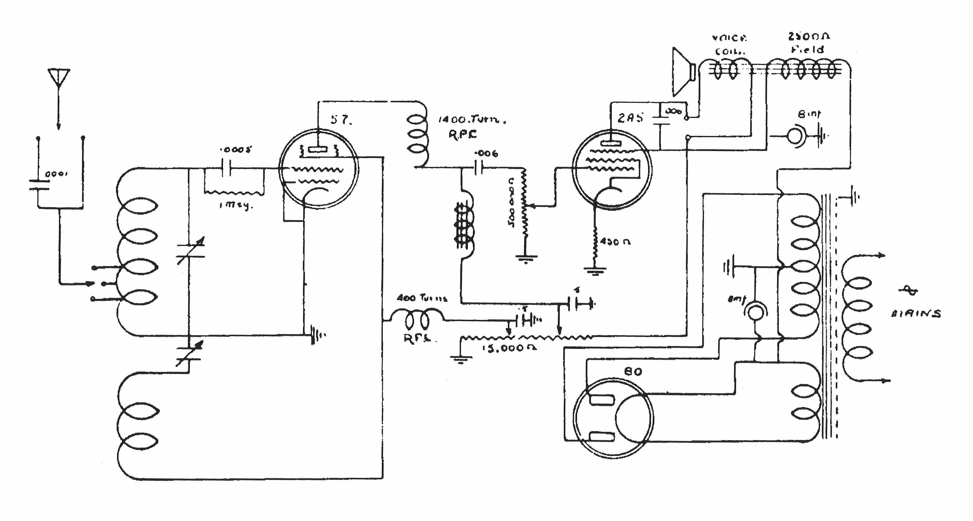 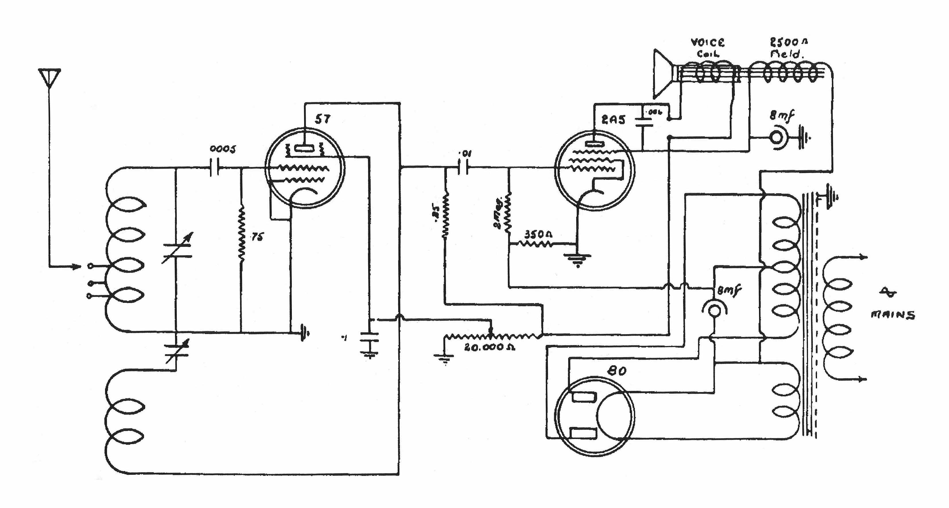 |
|
|
Return to top of page · Post #: 7 · Written at 2:22:35 AM on 7 March 2014.
|
|
|
|
Location: Perth, WA
Member since 7 May 2012 Member #: 1140 Postcount: 157 |
|
Hi Marc, 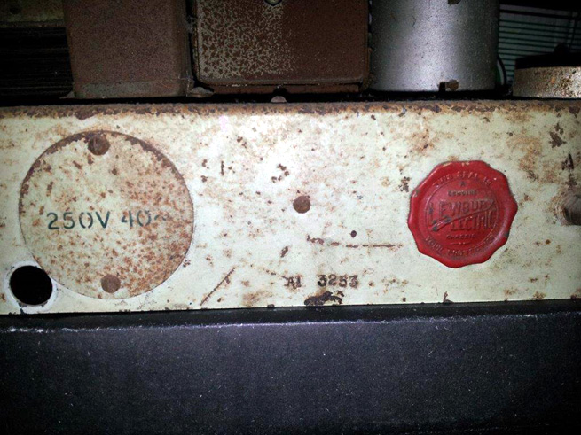 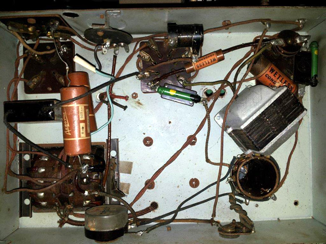 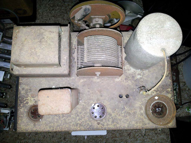 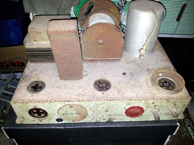 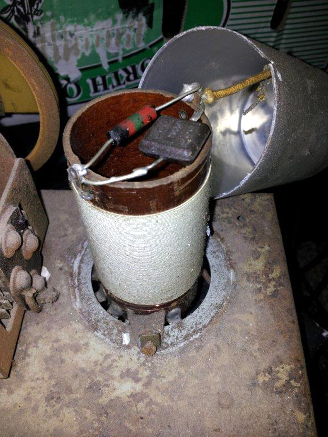 Cheers Vic |
|
|
Return to top of page · Post #: 8 · Written at 11:33:08 PM on 7 March 2014.
|
|
|
|
Location: Wangaratta, VIC
Member since 21 February 2009 Member #: 438 Postcount: 5720 |
|
Note the incorrect nomenclature for the 57 in the second drawing, also note the cathode resistor for 2A5 is virtually back bias for the 57. |
|
|
Return to top of page · Post #: 9 · Written at 10:17:18 AM on 8 March 2014.
|
|

|
Administrator
Location: Naremburn, NSW
Member since 15 November 2005 Member #: 1 Postcount: 7633 |
|
Pictures uploaded. ‾‾‾‾‾‾‾‾‾‾‾‾‾‾‾‾‾‾‾‾‾‾‾‾‾‾‾‾‾‾‾‾‾‾‾‾‾‾‾‾‾‾‾‾‾‾‾‾‾‾‾‾‾‾‾‾‾‾‾‾‾‾‾‾‾‾‾‾ A valve a day keeps the transistor away... |
|
|
Return to top of page · Post #: 10 · Written at 1:45:10 PM on 8 March 2014.
|
|
|
|
Location: Wangaratta, VIC
Member since 21 February 2009 Member #: 438 Postcount: 5720 |
|
Pretty obvious that someone has has a go at this before. |
|
|
Return to top of page · Post #: 11 · Written at 3:07:22 PM on 8 March 2014.
|
|
|
|
Location: Perth, WA
Member since 7 May 2012 Member #: 1140 Postcount: 157 |
|
Thanks Marc, |
|
|
Return to top of page · Post #: 12 · Written at 8:53:33 PM on 8 March 2014.
|
|
|
|
Location: Wangaratta, VIC
Member since 21 February 2009 Member #: 438 Postcount: 5720 |
|
The last bod left that a bit messy. I do not like the position of the rectangular block cap (cathode bypass?) it could be closer to the valve. |
|
|
Return to top of page · Post #: 13 · Written at 5:45:58 AM on 9 March 2014.
|
|
|
|
Location: Oradell, US
Member since 2 April 2010 Member #: 643 Postcount: 839 |
Looks like a superregenitive radio. The RF stage is rigged up to almost go into oscillation, thus creating gain. One of the pots controls this, go too far and you'll get squeals. Back off on it. See http://en.wikipedia.org/wiki/Regenerative_circuit. |
|
|
Return to top of page · Post #: 14 · Written at 4:11:47 AM on 10 March 2014.
|
|
|
|
Location: Perth, WA
Member since 7 May 2012 Member #: 1140 Postcount: 157 |
|
Hi Marc, |
|
|
Return to top of page · Post #: 15 · Written at 9:20:36 AM on 10 March 2014.
|
|
|
|
Location: Hobart, TAS
Member since 13 October 2013 Member #: 1430 Postcount: 25 |
|
Good morning Vic, |
|
|
You need to be a member to post comments on this forum.
|
|
Sign In
Vintage Radio and Television is proudly brought to you by an era where things were built with pride and made to last.
DISCLAIMER: Valve radios and televisions contain voltages that can deliver lethal shocks. You should not attempt to work on a valve radio or other electrical appliances unless you know exactly what you are doing and have gained some experience with electronics and working around high voltages. The owner, administrators and staff of Vintage Radio & Television will accept no liability for any damage, injury or loss of life that comes as a result of your use or mis-use of information on this website. Please read our Safety Warning before using this website.
WARNING: Under no circumstances should you ever apply power to a vintage radio, television or other electrical appliance you have acquired without first having it checked and serviced by an experienced person. Also, at no time should any appliance be connected to an electricity supply if the power cord is damaged. If in doubt, do not apply power.
Shintara - Keepin' It Real · VileSilencer - Maintain The Rage