
Wanted and For Sale
Forum home - Go back to Wanted and for sale
|
Aristone unit ID & hopefully Schematic
|
|
|
« Back ·
1 ·
Next »
|
|
|
Return to top of page · Post #: 1 · Written at 1:23:06 PM on 19 February 2014.
|
|
|
|
Location: Somewhere, USA
Member since 22 October 2013 Member #: 1437 Postcount: 896 |
|
Hi Guys, |
|
|
Return to top of page · Post #: 2 · Written at 4:12:32 PM on 19 February 2014.
|
|

|
Location: Wangaratta, VIC
Member since 21 February 2009 Member #: 438 Postcount: 5720 |
|
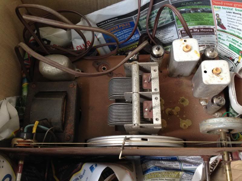
Its got 9 pins, that narrows the field. Most likely 6M5 |
|
|
Return to top of page · Post #: 3 · Written at 4:46:37 PM on 19 February 2014.
|
|
|
|
Location: Somewhere, USA
Member since 22 October 2013 Member #: 1437 Postcount: 896 |
|
I would have guessed 6M5 since I've seen a few other |
|
|
Return to top of page · Post #: 4 · Written at 5:59:13 PM on 19 February 2014.
|
|
|
|
Location: Blue Mountains, NSW
Member since 10 March 2013 Member #: 1312 Postcount: 401 |
|
The only four valve radiogram I can find that uses a 6BE6, 6M5 and 6V4 is a Precedent 415. The fourth valve is a 6N8 used as both an IF amp for radio and AF amp for records. |
|
|
Return to top of page · Post #: 5 · Written at 6:15:24 PM on 19 February 2014.
|
|
|
|
Location: Somewhere, USA
Member since 22 October 2013 Member #: 1437 Postcount: 896 |
|
This is a five valve set though, it's just that one is missing. |
|
|
Return to top of page · Post #: 6 · Written at 8:11:39 PM on 19 February 2014.
|
|
|
|
Location: Somewhere, USA
Member since 22 October 2013 Member #: 1437 Postcount: 896 |
|
Whoops.. Scraps, if you looked at the picture and counted valves, |
|
|
Return to top of page · Post #: 7 · Written at 12:25:16 PM on 20 February 2014.
|
|
|
|
Location: Somewhere, USA
Member since 22 October 2013 Member #: 1437 Postcount: 896 |
|
|
|
|
Return to top of page · Post #: 8 · Written at 8:58:19 PM on 24 February 2014.
|
|
|
|
Location: Somewhere, USA
Member since 22 October 2013 Member #: 1437 Postcount: 896 |
|
I brought this one back tonight woohoo! |
|
|
Return to top of page · Post #: 9 · Written at 7:20:19 AM on 25 February 2014.
|
|
|
|
Location: Blue Mountains, NSW
Member since 10 March 2013 Member #: 1312 Postcount: 401 |
|
See post 3 from GTC in this thread; |
|
|
Return to top of page · Post #: 10 · Written at 10:50:08 AM on 25 February 2014.
|
|
|
|
Location: Somewhere, USA
Member since 22 October 2013 Member #: 1437 Postcount: 896 |
|
Thanks |
|
|
« Back ·
1 ·
Next »
|
|
|
You need to be a member to post comments on this forum.
|
|

Sign In
Vintage Radio and Television is proudly brought to you by an era where things were built with pride and made to last.
DISCLAIMER: Valve radios and televisions contain voltages that can deliver lethal shocks. You should not attempt to work on a valve radio or other electrical appliances unless you know exactly what you are doing and have gained some experience with electronics and working around high voltages. The owner, administrators and staff of Vintage Radio & Television will accept no liability for any damage, injury or loss of life that comes as a result of your use or mis-use of information on this website. Please read our Safety Warning before using this website.
WARNING: Under no circumstances should you ever apply power to a vintage radio, television or other electrical appliance you have acquired without first having it checked and serviced by an experienced person. Also, at no time should any appliance be connected to an electricity supply if the power cord is damaged. If in doubt, do not apply power.
Shintara - Keepin' It Real · VileSilencer - Maintain The Rage