
Tech Talk
Forum home - Go back to Tech talk
|
Leader SG 11 repairs
|
|
|
Return to top of page · Post #: 1 · Written at 5:40:47 PM on 11 June 2019.
|
|
|
|
Location: Cargo, NSW
Member since 19 June 2018 Member #: 2256 Postcount: 96 |
|
This is a follow on from a previous post in Wanted and for Sale 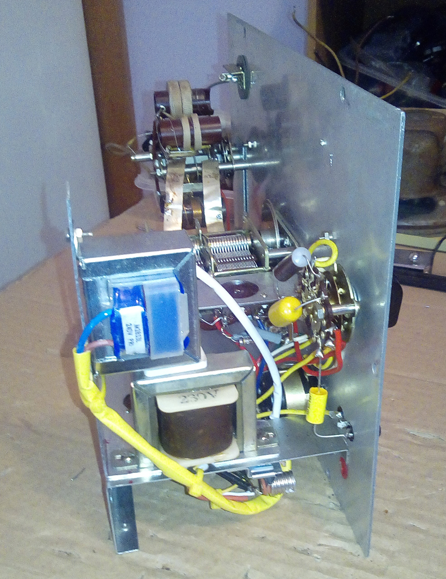 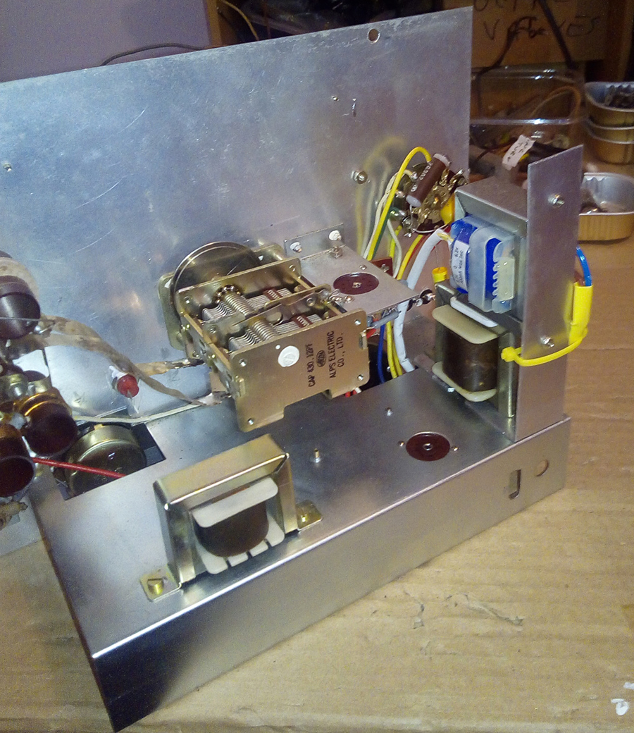 |
|
|
Return to top of page · Post #: 2 · Written at 10:39:38 PM on 11 June 2019.
|
|

|
Location: Wangaratta, VIC
Member since 21 February 2009 Member #: 438 Postcount: 5717 |
|
That appears pathetically low and does not appear on the valve data sheet. Catch 22 that sounds about right. They obviously run that low to get harmonics. |
|
|
Return to top of page · Post #: 3 · Written at 5:42:15 AM on 12 June 2019.
|
|
|
|
Location: Toongabbie, NSW
Member since 19 November 2015 Member #: 1828 Postcount: 1408 |
|
Hi Norm, somewhere around 70 volt or so is correct going by the circuit arrangement. |
|
|
Return to top of page · Post #: 4 · Written at 7:58:43 AM on 12 June 2019.
|
|
|
|
Location: Wangaratta, VIC
Member since 21 February 2009 Member #: 438 Postcount: 5717 |
|
I have the Instruction books (as may have been noted) for both the Dick Smith TE-20D clone and the SG-11. I did have a restored SG-11 however that and dollars got swapped for one with a fried transformer. |
|
|
Return to top of page · Post #: 5 · Written at 12:04:55 PM on 12 June 2019.
|
|
|
|
Location: Cargo, NSW
Member since 19 June 2018 Member #: 2256 Postcount: 96 |
|
Thanks Fred and Marcc. |
|
|
Return to top of page · Post #: 6 · Written at 12:16:03 PM on 12 June 2019.
|
|
|
|
Location: Toongabbie, NSW
Member since 19 November 2015 Member #: 1828 Postcount: 1408 |
|
Hi Norm, the readings in your last post look ok to me and 15ma sounds normal so no fault in the power supply to worry about. |
|
|
Return to top of page · Post #: 7 · Written at 2:31:24 AM on 15 June 2019.
|
|

|
Administrator
Location: Naremburn, NSW
Member since 15 November 2005 Member #: 1 Postcount: 7630 |
|
Photos uploaded. ‾‾‾‾‾‾‾‾‾‾‾‾‾‾‾‾‾‾‾‾‾‾‾‾‾‾‾‾‾‾‾‾‾‾‾‾‾‾‾‾‾‾‾‾‾‾‾‾‾‾‾‾‾‾‾‾‾‾‾‾‾‾‾‾‾‾‾‾ A valve a day keeps the transistor away... |
|
|
Return to top of page · Post #: 8 · Written at 5:31:51 AM on 15 June 2019.
|
|
|
|
Location: Toongabbie, NSW
Member since 19 November 2015 Member #: 1828 Postcount: 1408 |
|
Looked at photos, nicely done Norm almost looks original fitting! |
|
|
Return to top of page · Post #: 9 · Written at 6:33:36 PM on 15 June 2019.
|
|
|
|
Location: Wangaratta, VIC
Member since 21 February 2009 Member #: 438 Postcount: 5717 |
|
Looks nice but! I see an original brown jacketed oil filled cap: To me those look really nice decorating a bin. Whilst that is low voltage, I have found many oil filled caps to be as bad as Waxed paper. I tested a couple of that sort of cap in the unit that was here for leakage. Invariably on not ever seeing that type before: They failed leakage. So I tested the lot and they all failed. |
|
|
Return to top of page · Post #: 10 · Written at 9:10:49 PM on 20 June 2019.
|
|
|
|
Location: Cargo, NSW
Member since 19 June 2018 Member #: 2256 Postcount: 96 |
|
Marcc I replaced the oil filled cap as you pointed out, it actually measured OK but replaced it anyway |
|
|
Return to top of page · Post #: 11 · Written at 2:36:22 PM on 25 June 2019.
|
|
|
|
Location: Belrose, NSW
Member since 31 December 2015 Member #: 1844 Postcount: 2710 |
|
Those voltages are easily close enough that it should work as is. |
|
|
Return to top of page · Post #: 12 · Written at 2:10:59 PM on 6 August 2019.
|
|
|
|
Location: Cargo, NSW
Member since 19 June 2018 Member #: 2256 Postcount: 96 |
|
After a lot of fiddling around, decided the original power transformer secondary could also be faulty |
|
|
Return to top of page · Post #: 13 · Written at 6:56:28 PM on 6 August 2019.
|
|
|
|
Location: Toongabbie, NSW
Member since 19 November 2015 Member #: 1828 Postcount: 1408 |
|
Persistence wins out, well done. |
|
|
Return to top of page · Post #: 14 · Written at 8:07:49 PM on 6 August 2019.
|
|

|
Location: Sydney, NSW
Member since 28 January 2011 Member #: 823 Postcount: 6949 |
|
Good outcome. My LSG-11 died a while back and is sittting in the round tuit queue. |
|
|
Return to top of page · Post #: 15 · Written at 9:05:50 PM on 6 August 2019.
|
|
|
|
Location: Wangaratta, VIC
Member since 21 February 2009 Member #: 438 Postcount: 5717 |
|
Beware, at the risk of sucking eggs: There are two tests that relate to capacitors. |
|
|
You need to be a member to post comments on this forum.
|
|
Sign In
Vintage Radio and Television is proudly brought to you by an era where things were built with pride and made to last.
DISCLAIMER: Valve radios and televisions contain voltages that can deliver lethal shocks. You should not attempt to work on a valve radio or other electrical appliances unless you know exactly what you are doing and have gained some experience with electronics and working around high voltages. The owner, administrators and staff of Vintage Radio & Television will accept no liability for any damage, injury or loss of life that comes as a result of your use or mis-use of information on this website. Please read our Safety Warning before using this website.
WARNING: Under no circumstances should you ever apply power to a vintage radio, television or other electrical appliance you have acquired without first having it checked and serviced by an experienced person. Also, at no time should any appliance be connected to an electricity supply if the power cord is damaged. If in doubt, do not apply power.
Shintara - Keepin' It Real · VileSilencer - Maintain The Rage