
Tech Talk
Forum home - Go back to Tech talk
|
Capacitor Reformation circuitry
|
|
|
« Back ·
1 ·
Next »
|
|
|
Return to top of page · Post #: 1 · Written at 2:32:40 PM on 25 April 2019.
|
|

|
Location: Nildottie, SA
Member since 7 April 2018 Member #: 2236 Postcount: 43 |
|
Thanks to this forum I have found out about the need to reform capacitors. 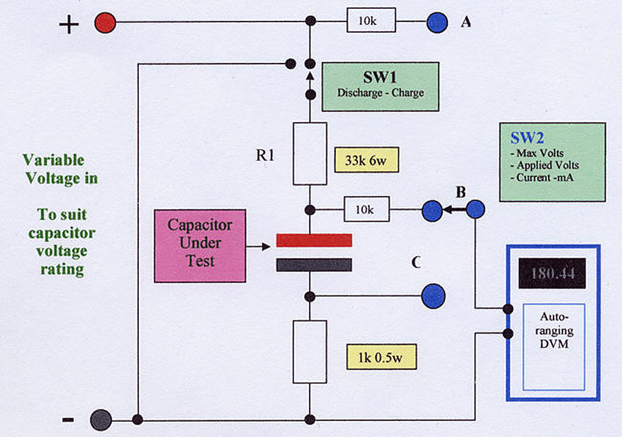 |
|
|
Return to top of page · Post #: 2 · Written at 2:56:22 PM on 25 April 2019.
|
|

|
Location: Wangaratta, VIC
Member since 21 February 2009 Member #: 438 Postcount: 5715 |
|
You only reform Electrolytic caps and that is with DC. There is trepidation before I even see a circuit. |
|
|
Return to top of page · Post #: 3 · Written at 3:54:55 PM on 25 April 2019.
|
|

|
Administrator
Location: Naremburn, NSW
Member since 15 November 2005 Member #: 1 Postcount: 7624 |
|
Photo uploaded. ‾‾‾‾‾‾‾‾‾‾‾‾‾‾‾‾‾‾‾‾‾‾‾‾‾‾‾‾‾‾‾‾‾‾‾‾‾‾‾‾‾‾‾‾‾‾‾‾‾‾‾‾‾‾‾‾‾‾‾‾‾‾‾‾‾‾‾‾ A valve a day keeps the transistor away... |
|
|
Return to top of page · Post #: 4 · Written at 7:48:49 PM on 25 April 2019.
|
|
|
|
Location: Wangaratta, VIC
Member since 21 February 2009 Member #: 438 Postcount: 5715 |
|
Anything running directly from the mains without a transformer, is to be considered intrinsically unsafe. Dimmers do not put out a good waveform. Even the reformers in my 1938 Valve & Circuit Tester use a transformer. |
|
|
Return to top of page · Post #: 5 · Written at 8:17:55 PM on 25 April 2019.
|
|
|
|
Administrator
Location: Naremburn, NSW
Member since 15 November 2005 Member #: 1 Postcount: 7624 |
|
With regard to reforming, I am one who just avoids it. All the bother with setting up to do the job and it ends up costing more than simply replacing worn condensers with new ones - to me, this, along with worrying about whether the reforming worked or not, just doesn't warrant the time spent on reforming. ‾‾‾‾‾‾‾‾‾‾‾‾‾‾‾‾‾‾‾‾‾‾‾‾‾‾‾‾‾‾‾‾‾‾‾‾‾‾‾‾‾‾‾‾‾‾‾‾‾‾‾‾‾‾‾‾‾‾‾‾‾‾‾‾‾‾‾‾ A valve a day keeps the transistor away... |
|
|
Return to top of page · Post #: 6 · Written at 3:48:56 AM on 26 April 2019.
|
|
|
|
Location: Nildottie, SA
Member since 7 April 2018 Member #: 2236 Postcount: 43 |
|
Point taken with the safety aspect. I did read that dimmers will damage transformers hence the direct AC. |
|
|
Return to top of page · Post #: 7 · Written at 8:06:38 AM on 26 April 2019.
|
|

|
Location: Hill Top, NSW
Member since 18 September 2015 Member #: 1801 Postcount: 2254 |
|
My "reforming" is pretty basic - turn on the radio for about a minute, turn it off for 10minutes, then turn it back on again. |
|
|
Return to top of page · Post #: 8 · Written at 3:02:09 PM on 26 April 2019.
|
|

|
Location: Sydney, NSW
Member since 26 April 2019 Member #: 2349 Postcount: 18 |
|
I think that circuit is ingenious, and a good way to explore the characteristics of vintage electros that you do come across e.g. ones that have not seen service over a number of decades. |
|
|
Return to top of page · Post #: 9 · Written at 3:15:45 PM on 26 April 2019.
|
|
|
|
Location: Wangaratta, VIC
Member since 21 February 2009 Member #: 438 Postcount: 5715 |
|
As noted I use mine more for testing than reforming. I do not bother attempting to reform the old red Ducons. The other thing I use it for is powering a "B" rail for odd ball faults, or if I think a filter cap has gone funny* (beware of voltage dividers). |
|
|
Return to top of page · Post #: 10 · Written at 9:10:59 PM on 26 April 2019.
|
|
|
|
Location: Sydney, NSW
Member since 26 April 2019 Member #: 2349 Postcount: 18 |
|
A good test/diagnostic for HV electros is a megger, switched to either 250 or 500v depending on the ratings of the cap being tested. |
|
|
Return to top of page · Post #: 11 · Written at 4:16:31 PM on 27 April 2019.
|
|
|
|
Location: Christchurch, NZ
Member since 4 December 2016 Member #: 2018 Postcount: 10 |
|
My method is to use a variable voltage DC source. Connect the capacitor negative to negative and fit a 10k resistor between the positive of the supply and the cap. Connect a DC voltmeter across the capacitor and raise the power supply voltage to around 100V. Watch the voltage across the cap. It will rise slowly, sometimes very slowly. When the voltage across the capacitor is within 10% of the supply voltage, raise the supply voltage again by another 100V. If a cap is beyond reforming, the voltage across it will not rise. As well, when the supply is disconnected, the voltage of a good capacitor will drop slowly whereas a poor one will drop much more quickly. |
|
|
Return to top of page · Post #: 12 · Written at 5:28:13 PM on 27 April 2019.
|
|
|
|
Location: Wangaratta, VIC
Member since 21 February 2009 Member #: 438 Postcount: 5715 |
|
N believe the formula for leakage is 0.1CV. draw un in uA. the old Lafayette RC bridge here says the limit is 10mA: No way would one with a leakage like that get a berth in a radio. |
|
|
Return to top of page · Post #: 13 · Written at 8:30:51 PM on 27 April 2019.
|
|
|
|
Location: Nildottie, SA
Member since 7 April 2018 Member #: 2236 Postcount: 43 |
|
Ok, my immediate problem is the lack of a variable DC supply. I will rectify that first. |
|
|
Return to top of page · Post #: 14 · Written at 5:32:35 AM on 3 May 2019.
|
|
|
|
Location: Belrose, NSW
Member since 31 December 2015 Member #: 1844 Postcount: 2710 |
|
I've had good results reforming large, expensive multi-section electros in 50's and 60's TVs (provided they are showing no signs of physical leaks and they were not made by UCC) by using the chassis's rectifier, all other valves removed, and a dim bulb. |
|
|
« Back ·
1 ·
Next »
|
|
|
You need to be a member to post comments on this forum.
|
|
Sign In
Vintage Radio and Television is proudly brought to you by an era where things were built with pride and made to last.
DISCLAIMER: Valve radios and televisions contain voltages that can deliver lethal shocks. You should not attempt to work on a valve radio or other electrical appliances unless you know exactly what you are doing and have gained some experience with electronics and working around high voltages. The owner, administrators and staff of Vintage Radio & Television will accept no liability for any damage, injury or loss of life that comes as a result of your use or mis-use of information on this website. Please read our Safety Warning before using this website.
WARNING: Under no circumstances should you ever apply power to a vintage radio, television or other electrical appliance you have acquired without first having it checked and serviced by an experienced person. Also, at no time should any appliance be connected to an electricity supply if the power cord is damaged. If in doubt, do not apply power.
Shintara - Keepin' It Real · VileSilencer - Maintain The Rage