
Tech Talk
Forum home - Go back to Tech talk
|
Phillips Model 114 with solid state rectifier
|
|
|
« Back ·
1 ·
Next »
|
|
|
Return to top of page · Post #: 1 · Written at 8:37:01 PM on 29 March 2019.
|
|

|
Location: Latham, ACT
Member since 21 February 2015 Member #: 1705 Postcount: 2234 |
|
This was one of my spare parts sets but I am rebuilding it now. It does work but it's a wonder. The rectifier was built using a old 6X5 base with the components sticking out the top. Bloody dangerous , the guy also terminated a 100UF electro onto one of the existing 16UF electros keeping it in circuit, again not good so its reverse engineering for me on this one.  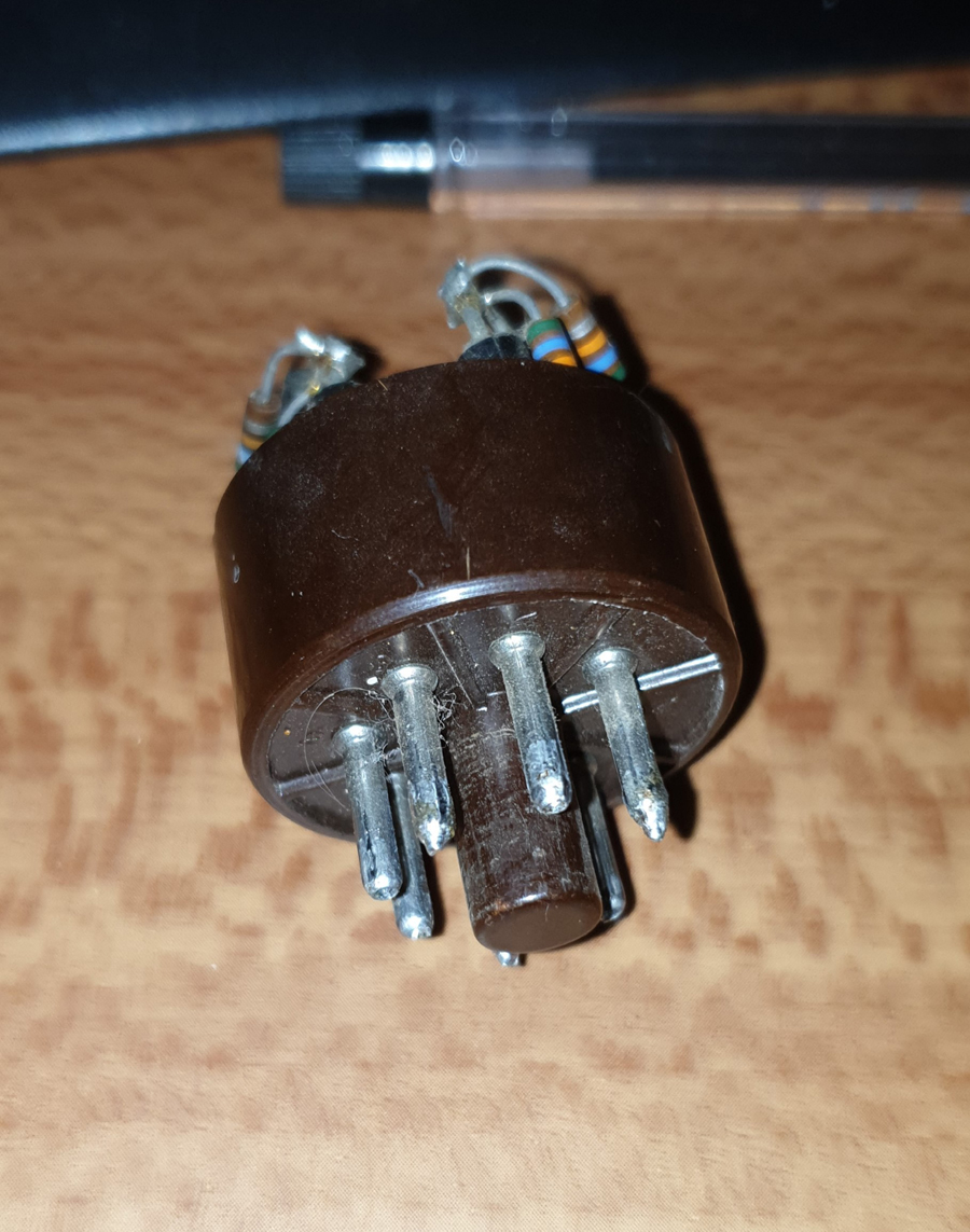  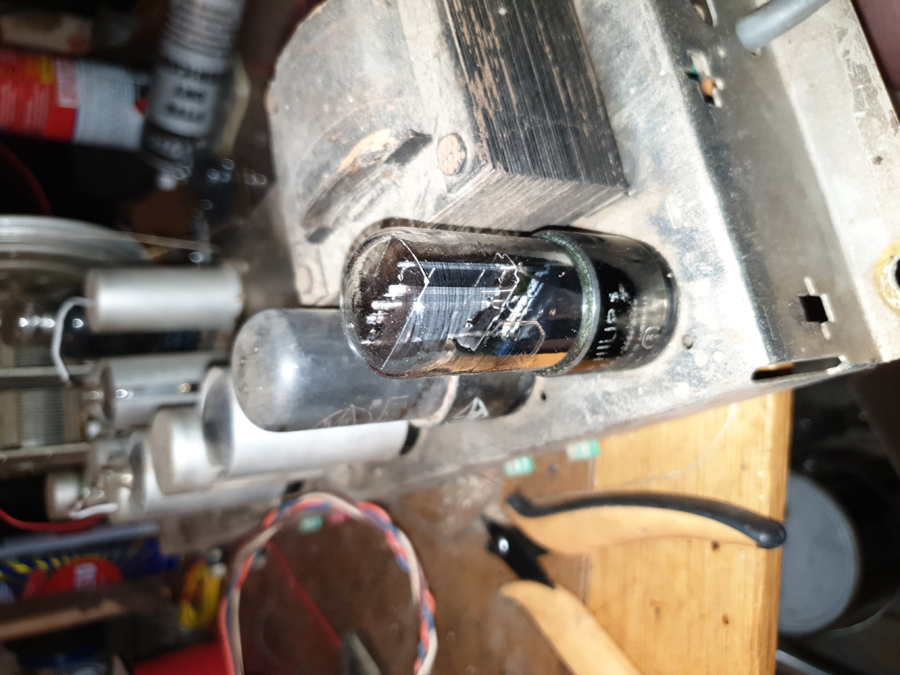 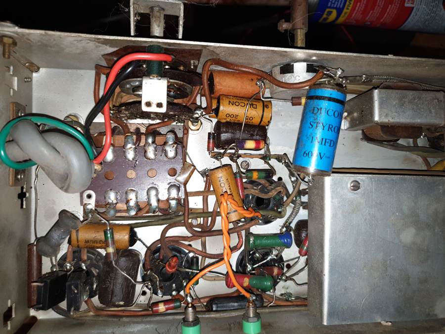 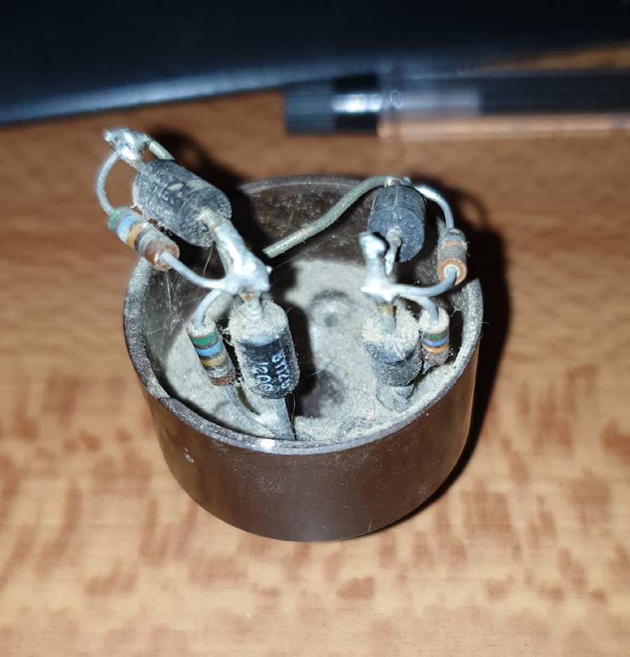  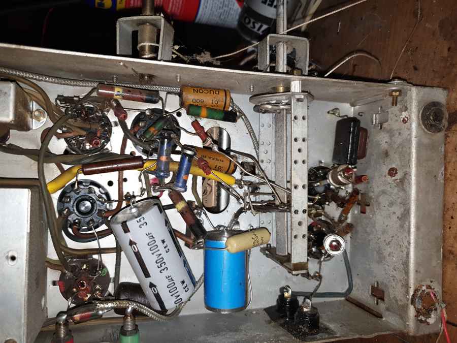 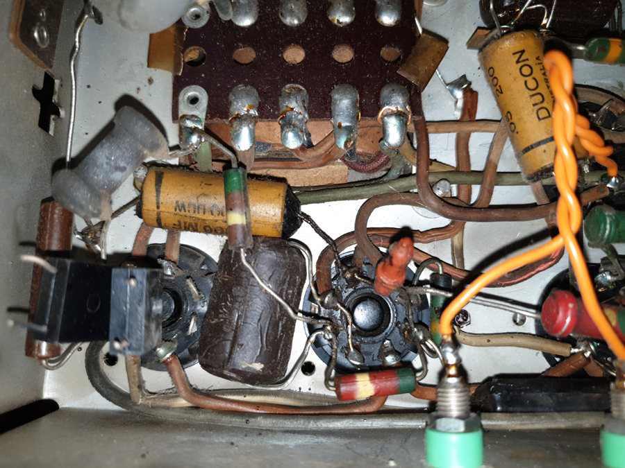 |
|
|
Return to top of page · Post #: 2 · Written at 10:46:06 PM on 29 March 2019.
|
|

|
Location: Sydney, NSW
Member since 28 January 2011 Member #: 823 Postcount: 6949 |
|
The rectifier was built using a old 6X5 base with the components sticking out the top. |
|
|
Return to top of page · Post #: 3 · Written at 12:19:39 PM on 30 March 2019.
|
|

|
Location: Penrith, NSW
Member since 7 April 2012 Member #: 1128 Postcount: 405 |
|
Hello all. 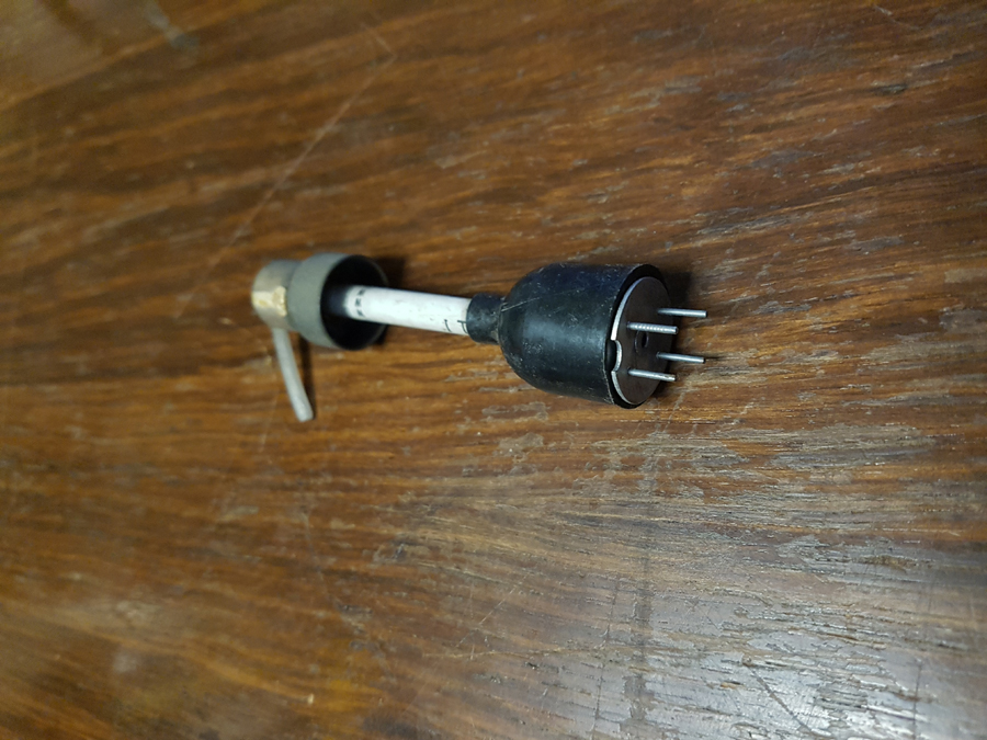 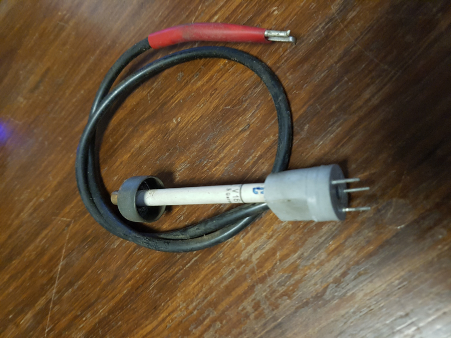 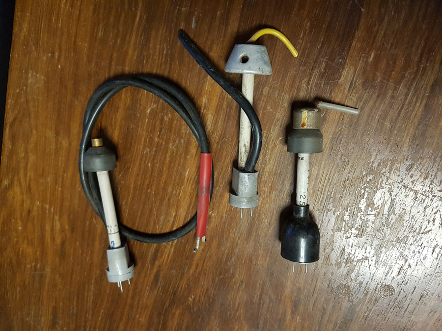 ‾‾‾‾‾‾‾‾‾‾‾‾‾‾‾‾‾‾‾‾‾‾‾‾‾‾‾‾‾‾‾‾‾‾‾‾‾‾‾‾‾‾‾‾‾‾‾‾‾‾‾‾‾‾‾‾‾‾‾‾‾‾‾‾‾‾‾‾ I love the smell of ozone in the morning. |
|
|
Return to top of page · Post #: 4 · Written at 5:01:17 PM on 30 March 2019.
|
|

|
Location: Wangaratta, VIC
Member since 21 February 2009 Member #: 438 Postcount: 5717 |
|
If it originally had a metal rectifier, it would indeed, develop more volts but still behave like a 5Y3 and create a surge voltage close to twice the loaded volts, so one has to watch the voltage rating of the caps. |
|
|
Return to top of page · Post #: 5 · Written at 5:40:04 PM on 31 March 2019.
|
|
|
|
Location: Latham, ACT
Member since 21 February 2015 Member #: 1705 Postcount: 2234 |
|
This set has now been recapped and is working but not enough volume. When I connect a antenna wire reception gets a little stronger but when I touch one tag on the tubing capacitor it comes on strong. Could this mean there is a resistor in the antenna circuit that's gone high or is it just a realignment. This set has been got at but is worth repairing and when it's complete I will have two model 114s. |
|
|
Return to top of page · Post #: 6 · Written at 6:36:07 PM on 31 March 2019.
|
|

|
Administrator
Location: Naremburn, NSW
Member since 15 November 2005 Member #: 1 Postcount: 7630 |
|
Photos uploaded to Posts 1 and 3. ‾‾‾‾‾‾‾‾‾‾‾‾‾‾‾‾‾‾‾‾‾‾‾‾‾‾‾‾‾‾‾‾‾‾‾‾‾‾‾‾‾‾‾‾‾‾‾‾‾‾‾‾‾‾‾‾‾‾‾‾‾‾‾‾‾‾‾‾ A valve a day keeps the transistor away... |
|
|
Return to top of page · Post #: 7 · Written at 6:58:20 PM on 31 March 2019.
|
|

|
Location: Hobart, TAS
Member since 31 July 2016 Member #: 1959 Postcount: 605 |
|
Sounds like it needs an antenna coil alignment as minimum. |
|
|
Return to top of page · Post #: 8 · Written at 7:23:37 PM on 31 March 2019.
|
|
|
|
Location: Latham, ACT
Member since 21 February 2015 Member #: 1705 Postcount: 2234 |
|
No not all the high value resistors, just the ones on the output valve. I found two resistors that must have been add ones and served no real purpose as they did nothing what so ever. |
|
|
Return to top of page · Post #: 9 · Written at 7:30:35 PM on 31 March 2019.
|
|
|
|
Location: Latham, ACT
Member since 21 February 2015 Member #: 1705 Postcount: 2234 |
|
That body end for resistor in my last photo on the bottom right went high as I was testing it. Even though it measured within tolerance I was sceptical and placed another resistor over it to lower the value and it just went off as I did that. I replaced it with a new 470 k and it made a world of difference. |
|
|
Return to top of page · Post #: 10 · Written at 7:50:12 PM on 31 March 2019.
|
|
|
|
Location: Wangaratta, VIC
Member since 21 February 2009 Member #: 438 Postcount: 5717 |
|
As noted I prefer to check resistors as I change caps. The highest attrition rate are 50K, 500K & quite often 100K and the plate resistors on the first audio (all high ones as for previous post). If you have an eye tube, that normally has a 1M resistor on the base and its rare to find a good one. |
|
|
Return to top of page · Post #: 11 · Written at 3:53:57 PM on 26 April 2019.
|
|

|
Location: Sydney, NSW
Member since 26 April 2019 Member #: 2349 Postcount: 18 |
|
Back to that 6X5 adapter with the Si diodes.....should not the original constructor pumped silicone over the components....we all have a tube of that in our garage...don't we? |
|
|
Return to top of page · Post #: 12 · Written at 6:13:03 PM on 27 April 2019.
|
|
|
|
Location: Hobart, TAS
Member since 31 July 2016 Member #: 1959 Postcount: 605 |
|
Silicon is a very bad insulator in general. |
|
|
Return to top of page · Post #: 13 · Written at 7:10:22 AM on 29 April 2019.
|
|
|
|
Location: Sydney, NSW
Member since 26 April 2019 Member #: 2349 Postcount: 18 |
|
Some silicons are guaranteed for 20years. |
|
|
« Back ·
1 ·
Next »
|
|
|
You need to be a member to post comments on this forum.
|
|
Sign In
Vintage Radio and Television is proudly brought to you by an era where things were built with pride and made to last.
DISCLAIMER: Valve radios and televisions contain voltages that can deliver lethal shocks. You should not attempt to work on a valve radio or other electrical appliances unless you know exactly what you are doing and have gained some experience with electronics and working around high voltages. The owner, administrators and staff of Vintage Radio & Television will accept no liability for any damage, injury or loss of life that comes as a result of your use or mis-use of information on this website. Please read our Safety Warning before using this website.
WARNING: Under no circumstances should you ever apply power to a vintage radio, television or other electrical appliance you have acquired without first having it checked and serviced by an experienced person. Also, at no time should any appliance be connected to an electricity supply if the power cord is damaged. If in doubt, do not apply power.
Shintara - Keepin' It Real · VileSilencer - Maintain The Rage