
Tech Talk
Forum home - Go back to Tech talk
|
Oceanic Multi Band Receiver
|
|
|
« Back ·
1 ·
Next »
|
|
|
Return to top of page · Post #: 1 · Written at 1:42:51 PM on 23 February 2019.
|
|
|
|
Location: Kanahooka, NSW
Member since 18 November 2016 Member #: 2012 Postcount: 712 |
|
Hi all, I need a circuit and preferably a service manual for this multi Band reciever. I will send some pictures to Brad and hopefully when he has time they can be added to this thread. It bears no model number anywhere. Not sure why I bought it. It is a tranistor mains battery set. The power transformer has basically an open circuit primary very high resistance. On battery it sometimes works after a delayed start. The speaker was manufactured in Taiwan. It will be quite nasty to remove the chassis without a service manual. It might be better as a door stop. 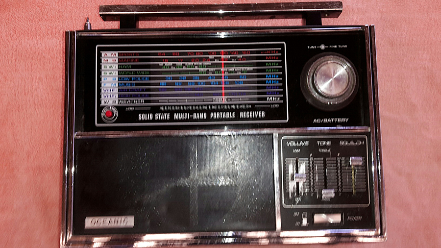 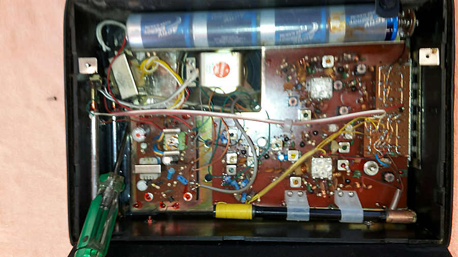   |
|
|
Return to top of page · Post #: 2 · Written at 6:18:51 PM on 25 February 2019.
|
|

|
Administrator
Location: Naremburn, NSW
Member since 15 November 2005 Member #: 1 Postcount: 7630 |
|
Photos uploaded. ‾‾‾‾‾‾‾‾‾‾‾‾‾‾‾‾‾‾‾‾‾‾‾‾‾‾‾‾‾‾‾‾‾‾‾‾‾‾‾‾‾‾‾‾‾‾‾‾‾‾‾‾‾‾‾‾‾‾‾‾‾‾‾‾‾‾‾‾ A valve a day keeps the transistor away... |
|
|
Return to top of page · Post #: 3 · Written at 7:27:00 PM on 25 February 2019.
|
|

|
Location: Hobart, TAS
Member since 31 July 2016 Member #: 1959 Postcount: 605 |
|
There are a lot of steps of normal diagnostics that would probably get this going OK without having a circuit or service manual. |
|
|
Return to top of page · Post #: 4 · Written at 7:32:17 PM on 25 February 2019.
|
|

|
Location: Sydney, NSW
Member since 28 January 2011 Member #: 823 Postcount: 6949 |
|
That strikes me as a badge-engineered radio. Let us know the transistor types and counts thereof in it. |
|
|
Return to top of page · Post #: 5 · Written at 10:06:15 PM on 25 February 2019.
|
|

|
Location: Wangaratta, VIC
Member since 21 February 2009 Member #: 438 Postcount: 5717 |
|
I don't think I would be messing with the transformer just yet, if it's playing up on batteries. It could be anything from a dry joint, to a dodgy on off switch, to the contact of the batteries themselves; even a dry joint on the board (they're still popular). Some of those slider pots can give trouble |
|
|
Return to top of page · Post #: 6 · Written at 11:08:07 AM on 26 February 2019.
|
|
|
|
Location: Kanahooka, NSW
Member since 18 November 2016 Member #: 2012 Postcount: 712 |
|
Thank you Brad once again for uploading the photos. |
|
|
Return to top of page · Post #: 7 · Written at 1:31:11 PM on 26 February 2019.
|
|

|
Location: Hill Top, NSW
Member since 18 September 2015 Member #: 1801 Postcount: 2255 |
|
Looks like the little knob at the top of the FM antenna is missing. |
|
|
Return to top of page · Post #: 8 · Written at 8:39:46 PM on 26 February 2019.
|
|
|
|
Location: Wangaratta, VIC
Member since 21 February 2009 Member #: 438 Postcount: 5717 |
|
There are pressures to distract. I have two engines that need serious attention: But not during bushfire season. I am working my way through the Mens Sheds cables & such. & as mentioned the radio section has around five fixers in the line. The days are really to short at the moment. |
|
|
Return to top of page · Post #: 9 · Written at 4:23:24 PM on 27 February 2019.
|
|
|
|
Location: Kanahooka, NSW
Member since 18 November 2016 Member #: 2012 Postcount: 712 |
|
Hello again from Jimb. |
|
|
Return to top of page · Post #: 10 · Written at 4:58:47 PM on 27 February 2019.
|
|
|
|
Location: Sydney, NSW
Member since 28 January 2011 Member #: 823 Postcount: 6949 |
|
Do a count of the transistor types and let us know. There may be a schematic available for it. |
|
|
Return to top of page · Post #: 11 · Written at 5:19:47 PM on 27 February 2019.
|
|
|
|
Location: Kanahooka, NSW
Member since 18 November 2016 Member #: 2012 Postcount: 712 |
|
Thanks GTC. |
|
|
Return to top of page · Post #: 12 · Written at 4:05:08 PM on 28 February 2019.
|
|
|
|
Location: Kanahooka, NSW
Member since 18 November 2016 Member #: 2012 Postcount: 712 |
|
Hello GTC. |
|
|
Return to top of page · Post #: 13 · Written at 4:18:28 PM on 28 February 2019.
|
|
|
|
Location: Sydney, NSW
Member since 28 January 2011 Member #: 823 Postcount: 6949 |
|
not able to see transistor types without twisting and bending them |
|
|
« Back ·
1 ·
Next »
|
|
|
You need to be a member to post comments on this forum.
|
|
Sign In
Vintage Radio and Television is proudly brought to you by an era where things were built with pride and made to last.
DISCLAIMER: Valve radios and televisions contain voltages that can deliver lethal shocks. You should not attempt to work on a valve radio or other electrical appliances unless you know exactly what you are doing and have gained some experience with electronics and working around high voltages. The owner, administrators and staff of Vintage Radio & Television will accept no liability for any damage, injury or loss of life that comes as a result of your use or mis-use of information on this website. Please read our Safety Warning before using this website.
WARNING: Under no circumstances should you ever apply power to a vintage radio, television or other electrical appliance you have acquired without first having it checked and serviced by an experienced person. Also, at no time should any appliance be connected to an electricity supply if the power cord is damaged. If in doubt, do not apply power.
Shintara - Keepin' It Real · VileSilencer - Maintain The Rage