
Tech Talk
Forum home - Go back to Tech talk
|
Astor Mickey CN High B+
|
|
|
Return to top of page · Post #: 1 · Written at 7:52:40 AM on 10 February 2019.
|
|
|
|
Location: Mount Cotton, QLD
Member since 20 February 2018 Member #: 2214 Postcount: 134 |
|
I have a Astor Mickey CN model which has a B+ of 149V. The schematic suggests it should be about 110V. This model uses a 32L7GT combined output - half wave rectifier valve, the plate voltage specification for this valve is 90V but it's running at 139V. The radio works very well. |
|
|
Return to top of page · Post #: 2 · Written at 9:30:49 AM on 10 February 2019.
|
|
|
|
Location: Oradell, US
Member since 2 April 2010 Member #: 643 Postcount: 836 |
|
A possible solution would be to add a resistor, 1K 2 watts, and a bypass cap say 100μF at 50V, between the 32L7 cathode resistor and the radio ground (where that cathode resistor used to connect to). And also move the control grid's resistor to the point between the original cathode cap and the new 1K resistor with new bypass cap. What this is to do is drop the voltage between the 32L7 output cathode and the output plate (not the rectifier ones). By elevating the voltage on the output cathode. The rest of the radio will still see extra B+. but you said that the radio is working well this way, and the RF and IF tubes do work better with higher (but within spec) B+ voltage. 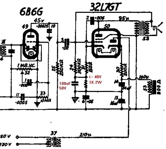 |
|
|
Return to top of page · Post #: 3 · Written at 12:14:26 PM on 10 February 2019.
|
|
|
|
Location: Mount Cotton, QLD
Member since 20 February 2018 Member #: 2214 Postcount: 134 |
|
Thanks Wa2ise, appreciate your help. I'll wait for your mod drawing to be uploaded but I think I understand what you are getting at. Cheers! |
|
|
Return to top of page · Post #: 4 · Written at 7:54:44 PM on 10 February 2019.
|
|

|
Location: Wangaratta, VIC
Member since 21 February 2009 Member #: 438 Postcount: 5692 |
|
Note the 210V is AC: Also note the position of the first 24μF cap. The 200 Ohm resistor makes it a choke input filter. There should be no cap directly on the cathode. If there is it will produce more voltage. The rectifier is quoted at 125V max 60mA. Capacitor input filter, which it isn't. |
|
|
Return to top of page · Post #: 5 · Written at 9:52:18 AM on 11 February 2019.
|
|
|
|
Location: Mount Cotton, QLD
Member since 20 February 2018 Member #: 2214 Postcount: 134 |
|
Hi Marc, thanks once again for your help. I have checked the ideas you have raised as below: |
|
|
Return to top of page · Post #: 6 · Written at 1:52:03 PM on 11 February 2019.
|
|
|
|
Location: Wangaratta, VIC
Member since 21 February 2009 Member #: 438 Postcount: 5692 |
|
Are those the old waxed paper caps or new ones? The plate bypass cap on the audio is the most likely to fail. If its old its probably leaking (a resistor) & should be removed ASAP before it turns into a short. If they are waxed paper and old. they and all of the old electrolytic's should be systematically removed & transferred to the bin. |
|
|
Return to top of page · Post #: 7 · Written at 5:52:25 PM on 11 February 2019.
|
|
|
|
Location: Mount Cotton, QLD
Member since 20 February 2018 Member #: 2214 Postcount: 134 |
|
All the caps have been replaced as well as any of resistors that measured high. I rechecked and all the replacement components are the correct value. |
|
|
Return to top of page · Post #: 8 · Written at 6:44:23 PM on 11 February 2019.
|
|
|
|
Location: Wangaratta, VIC
Member since 21 February 2009 Member #: 438 Postcount: 5692 |
|
With the 32L7's pentode cathode, (pin 8) the only cap shown from plate to it. pin 3 to pin 8. Do make sure that you are reading pins correctly. http://frank.yueksel.org/sheets/093/3/32L7GT.pdf |
|
|
Return to top of page · Post #: 9 · Written at 7:16:56 PM on 11 February 2019.
|
|
|
|
Location: Mount Cotton, QLD
Member since 20 February 2018 Member #: 2214 Postcount: 134 |
|
I have pin reading down pat |
|
|
Return to top of page · Post #: 10 · Written at 8:13:05 PM on 11 February 2019.
|
|
|
|
Location: Mount Cotton, QLD
Member since 20 February 2018 Member #: 2214 Postcount: 134 |
|
10mf wasn't a success, bit more hum and made little difference to the voltages. I upped the choke resistor from 200 to 300 Ohms and it brings the voltages within 20% of those stated without generating too much heat. The radio is working well and I'll leave it as is. I don't expect it will get much use. |
|
|
Return to top of page · Post #: 11 · Written at 8:31:28 PM on 11 February 2019.
|
|
|
|
Location: Wangaratta, VIC
Member since 21 February 2009 Member #: 438 Postcount: 5692 |
|
Yeh! We can but only try. Normally if one want's to take the stress off of the cathode, which a too big cap can strip, they use a smaller cap first, or none. |
|
|
Return to top of page · Post #: 12 · Written at 9:37:58 PM on 11 February 2019.
|
|
|
|
Location: Mount Cotton, QLD
Member since 20 February 2018 Member #: 2214 Postcount: 134 |
|
Hi Marc, |
|
|
Return to top of page · Post #: 13 · Written at 11:06:29 AM on 12 February 2019.
|
|
|
|
Location: Belrose, NSW
Member since 31 December 2015 Member #: 1844 Postcount: 2696 |
|
A quick check of your meter can be made by measuring a new unused alkaline cell. You should get 1.62 volts. |
|
|
Return to top of page · Post #: 14 · Written at 6:05:55 PM on 12 February 2019.
|
|
|
|
Location: Mount Cotton, QLD
Member since 20 February 2018 Member #: 2214 Postcount: 134 |
|
Hi Ian, thanks |
|
|
Return to top of page · Post #: 15 · Written at 6:33:28 PM on 12 February 2019.
|
|

|
Administrator
Location: Naremburn, NSW
Member since 15 November 2005 Member #: 1 Postcount: 7612 |
|
Circuit diagrams uploaded to Posts 1 and 2. ‾‾‾‾‾‾‾‾‾‾‾‾‾‾‾‾‾‾‾‾‾‾‾‾‾‾‾‾‾‾‾‾‾‾‾‾‾‾‾‾‾‾‾‾‾‾‾‾‾‾‾‾‾‾‾‾‾‾‾‾‾‾‾‾‾‾‾‾ A valve a day keeps the transistor away... |
|
|
You need to be a member to post comments on this forum.
|
|
 I'll put it back as it should be.
Sign In
Vintage Radio and Television is proudly brought to you by an era where things were built with pride and made to last.
DISCLAIMER: Valve radios and televisions contain voltages that can deliver lethal shocks. You should not attempt to work on a valve radio or other electrical appliances unless you know exactly what you are doing and have gained some experience with electronics and working around high voltages. The owner, administrators and staff of Vintage Radio & Television will accept no liability for any damage, injury or loss of life that comes as a result of your use or mis-use of information on this website. Please read our Safety Warning before using this website.
WARNING: Under no circumstances should you ever apply power to a vintage radio, television or other electrical appliance you have acquired without first having it checked and serviced by an experienced person. Also, at no time should any appliance be connected to an electricity supply if the power cord is damaged. If in doubt, do not apply power.
Shintara - Keepin' It Real · VileSilencer - Maintain The Rage