
Tech Talk
Forum home - Go back to Tech talk
|
Unusual Power-Amp circuit: Pros/Cons?
|
|
|
Return to top of page · Post #: 1 · Written at 3:57:16 PM on 9 October 2018.
|
|
|
Location: Silver City WI, US
Member since 10 May 2013 Member #: 1340 Postcount: 977 |
|
Never seen this before: |
|
|
Return to top of page · Post #: 2 · Written at 4:35:44 PM on 9 October 2018.
|
|

|
Location: Wangaratta, VIC
Member since 21 February 2009 Member #: 438 Postcount: 5715 |
|
Could be an interesting circuit study. They have a download thing but, the Malware program stops it in its tracks and locks it up. |
|
|
Return to top of page · Post #: 3 · Written at 5:15:11 PM on 9 October 2018.
|
|

|
Location: Sydney, NSW
Member since 28 January 2011 Member #: 823 Postcount: 6949 |
|
They have a download thing but, the Malware program stops it in its tracks and locks it up. |
|
|
Return to top of page · Post #: 4 · Written at 5:31:40 PM on 9 October 2018.
|
|
|
|
Location: Sydney, NSW
Member since 28 January 2011 Member #: 823 Postcount: 6949 |
|
Self-split (no phase inverter). Actually a pretty old idea, beloved of some guitar amp manufacturers. |
|
|
Return to top of page · Post #: 5 · Written at 10:14:15 PM on 9 October 2018.
|
|
|
|
Location: Silver City WI, US
Member since 10 May 2013 Member #: 1340 Postcount: 977 |
|
Thanks GTC for interesting link. |
|
|
Return to top of page · Post #: 6 · Written at 7:36:03 AM on 10 October 2018.
|
|
|
|
Location: Toongabbie, NSW
Member since 19 November 2015 Member #: 1828 Postcount: 1407 |
|
In my Radiotron Designers Handbook (Radio Designers Handbook 1967 7th imp) push pull amplifers, phase splitters et al are covered in excruciating detail. |
|
|
Return to top of page · Post #: 7 · Written at 9:25:36 AM on 10 October 2018.
|
|
|
|
Location: Wangaratta, VIC
Member since 21 February 2009 Member #: 438 Postcount: 5715 |
|
I did have a look at the Philips one with 6M5. typically Phililps with back bias & the bypass cap across it. However, the phase shift from the cathode of the other PP tube is the interesting bit. |
|
|
Return to top of page · Post #: 8 · Written at 2:43:55 PM on 10 October 2018.
|
|
|
|
Location: Belrose, NSW
Member since 31 December 2015 Member #: 1844 Postcount: 2710 |
|
Fred's point about driving the valves with cathode followers is a valid one. If you are building a guitar amplifier, you want max power without worrying too much about distortion. The cathode followers allow you to drive the output grids positive so they conduct harder and you avoid the pump-up (more negative) of the bias voltage that would normally occur when you drive to output towards clipping. My modelling shows nearly twice available power and the clipping is gradual, not messy like it is otherwise. |
|
|
Return to top of page · Post #: 9 · Written at 9:04:37 PM on 10 October 2018.
|
|
|
|
Location: Wangaratta, VIC
Member since 21 February 2009 Member #: 438 Postcount: 5715 |
|
Sometimes with transistors, that can be one step too far, if the polarisation is wrong. The MOSFETS really can handle a lot of power, whilst the rest of the circuit doesn't have to. By that comment, one notes the transistor is normally operated in series with the speaker (no transformer); I have seen a couple of examples where the VC tube of the speaker has been crushed when driven into the magnet. |
|
|
Return to top of page · Post #: 10 · Written at 4:16:56 PM on 11 October 2018.
|
|
|
|
Location: Belrose, NSW
Member since 31 December 2015 Member #: 1844 Postcount: 2710 |
|
Well Marc you make a valid point re polarisation, There's no such thing as a PNP valve!! |
|
|
Return to top of page · Post #: 11 · Written at 5:36:50 PM on 11 October 2018.
|
|
|
|
Location: Sydney, NSW
Member since 28 January 2011 Member #: 823 Postcount: 6949 |
|
Polarity where there is DC is important |
|
|
Return to top of page · Post #: 12 · Written at 9:39:56 PM on 11 October 2018.
|
|
|
|
Location: Wangaratta, VIC
Member since 21 February 2009 Member #: 438 Postcount: 5715 |
|
The point with a transformer couple with a valve like 6V6, is that there is no DC if its just driving a speaker. |
|
|
Return to top of page · Post #: 13 · Written at 4:30:16 PM on 12 October 2018.
|
|
|
|
Location: Silver City WI, US
Member since 10 May 2013 Member #: 1340 Postcount: 977 |
|
Listened to it today with experienced audiophile familiar with amps of that era: It sounded very smooth, he rates it a strong '8-out-of-10', with "solid deep bass" despite its smaller output transformer. 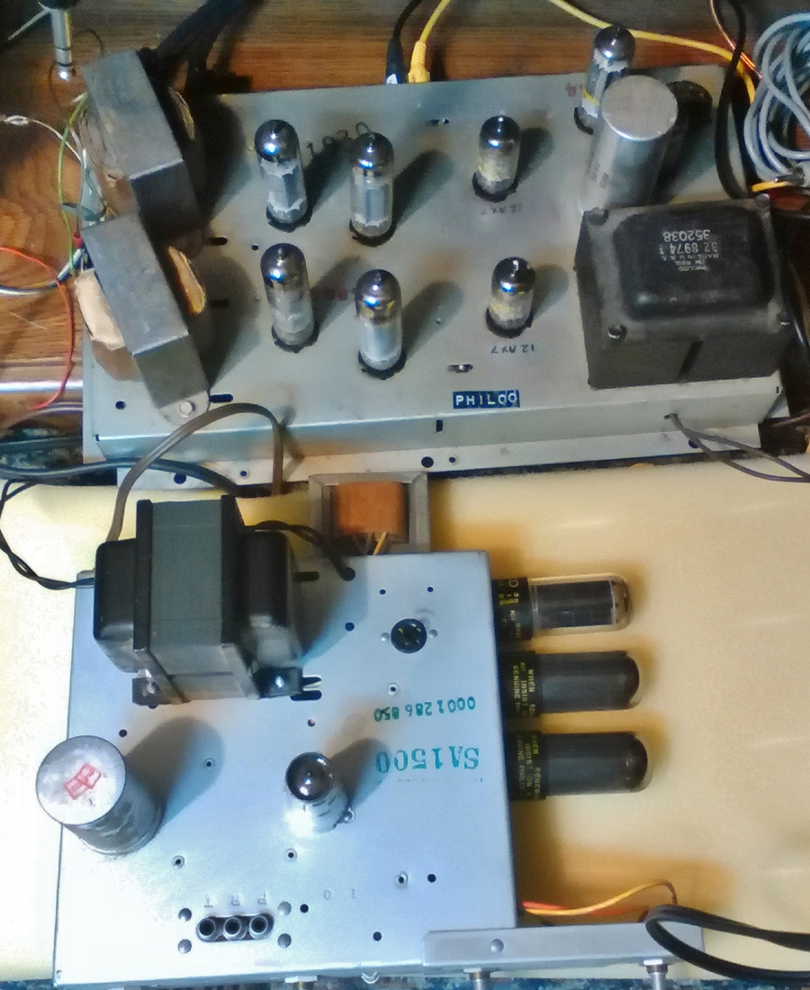 |
|
|
Return to top of page · Post #: 14 · Written at 4:18:44 AM on 13 October 2018.
|
|

|
Administrator
Location: Naremburn, NSW
Member since 15 November 2005 Member #: 1 Postcount: 7624 |
|
Photo uploaded to Post 13. ‾‾‾‾‾‾‾‾‾‾‾‾‾‾‾‾‾‾‾‾‾‾‾‾‾‾‾‾‾‾‾‾‾‾‾‾‾‾‾‾‾‾‾‾‾‾‾‾‾‾‾‾‾‾‾‾‾‾‾‾‾‾‾‾‾‾‾‾ A valve a day keeps the transistor away... |
|
|
Return to top of page · Post #: 15 · Written at 10:44:47 AM on 28 October 2018.
|
|

|
Location: Beechmont, QLD
Member since 10 April 2009 Member #: 465 Postcount: 109 |
|
|
|
|
You need to be a member to post comments on this forum.
|
|

Sign In
Vintage Radio and Television is proudly brought to you by an era where things were built with pride and made to last.
DISCLAIMER: Valve radios and televisions contain voltages that can deliver lethal shocks. You should not attempt to work on a valve radio or other electrical appliances unless you know exactly what you are doing and have gained some experience with electronics and working around high voltages. The owner, administrators and staff of Vintage Radio & Television will accept no liability for any damage, injury or loss of life that comes as a result of your use or mis-use of information on this website. Please read our Safety Warning before using this website.
WARNING: Under no circumstances should you ever apply power to a vintage radio, television or other electrical appliance you have acquired without first having it checked and serviced by an experienced person. Also, at no time should any appliance be connected to an electricity supply if the power cord is damaged. If in doubt, do not apply power.
Shintara - Keepin' It Real · VileSilencer - Maintain The Rage