Welcome to Australia's only Vintage Radio and Television discussion forums. You are not logged in. Please log in below, apply for an account or retrieve your password.
Australian Vintage Radio Forums
  Home  ·  About Us  ·  Discussion Forums  ·  Glossary  ·  Outside Links  ·  Policies  ·  Services Directory  ·  Safety Warnings  ·  Tutorials

Tech Talk

Forum home - Go back to Tech talk

 1939 STC 633 Console ... original dealer conversion for DC mains (?)
« Back · 1 · 2 · Next »
 Return to top of page · Post #: 1 · Written at 6:36:23 PM on 30 August 2018.
Nhanwell's Gravatar
 Location: Mount Lawley, WA
 Member since 12 September 2017
 Member #: 2167
 Postcount: 49

I've had this console since the early 90's when I bought the contents of an old radio shop in country WA.
Like everything else it's been waiting 20 plus years for my "retirement" and for some attention.

I remember plugging it in when I first acquired it. Why I did so without even a cursory inspection now alludes me. Ok, I was younger and more foolish then! But, it worked (even the magic eye). However, my attention was drawn to a bright light coming from the back of the cabinet. There was this huge light bulb in the middle of the chassis! Ooops - its an AC/DC set! I quickly unplugged it and put it into storage.

Roll on some 25 years and I'm rummaging through the contents under the stairs and I take another look at the STC console. Has it's time come to be resurrected?

I noted down the chassis number and valve line up from the rear sticker ( 6U7G, 6K8G, 6U7G, 6AG6G, 5Z4G & magic eye 6U5?) and went to RadioMuseum in search of a circuit diagram.

It is listed as an AC set!! How come there is a big light globe/barreter on the chassis?

I dragged the set out and had a closer look -- there is a manufactured plate housing a large choke, wire wound dropper (on asbestos?) and base for the barreter/globe. No evidence of the original mains transformer.

The actual rectifier was in fact a 25YG (not a 5Z4G) .

Looking under the chassis revealed one side of the mains lead was soldered to the chassis, the other side to the anodes of the rectifier and the barreter. The "RF Earth" lead was wired via a capacitor to chassis.

The set had definitely been converted for AC/DC operation at some stage.

Coincidentally, I came across this article by Lloyd Butler on DC mains and implications for radio in Murray Bridge. He describes how the dealer there used to convert AC AWA sets for operation on DC mains.

http://www.qsl.net/vk5br/Operation_on_DC_Mains.htm

Looks like I have a STC console that was converted and delivered to the customer to run on DC.
The base plate for the conversion is made of the same pinky/gold anodised metal as the main chassis. The cutouts look well machined and not a "one off" job. Could this have been an STC manufactured conversion?

Unfortunately, there is no visible marking on the audio output valve on this set.. so not sure if the original 6AG6G was replaced by a lower heater current 25V version or not. At this stage I haven't looked as to how the heaters have been wired.

I will not be restoring it as an AC/DC set.

If I find a suitable mains transformer from a donor set in the attic, I'll resurrect it otherwise it will remain cordless as an ornament Wink


Regards

Nigel

STC Console Radio
STC Console Radio
STC Console Radio
STC Console Radio
STC Console Radio


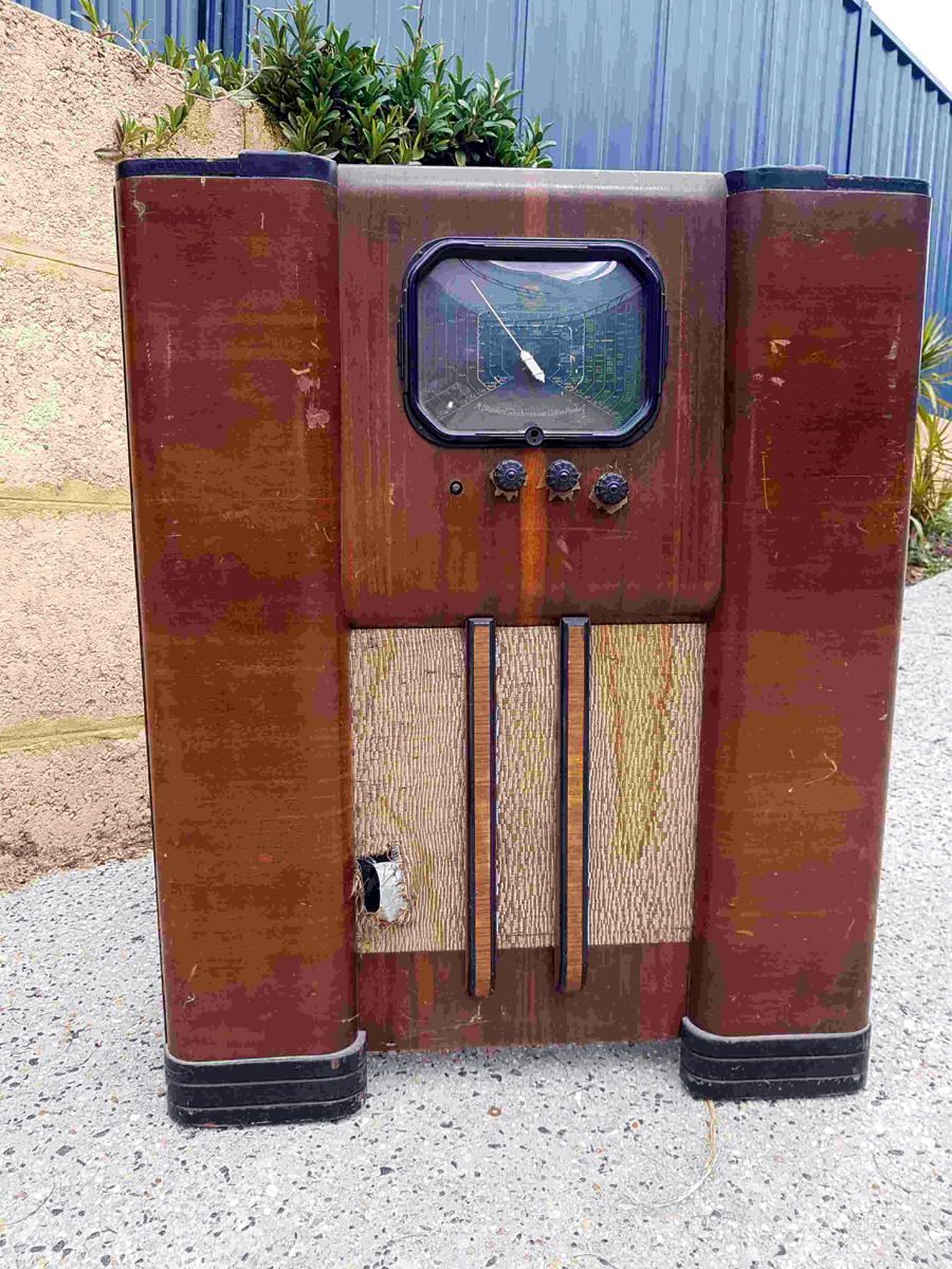
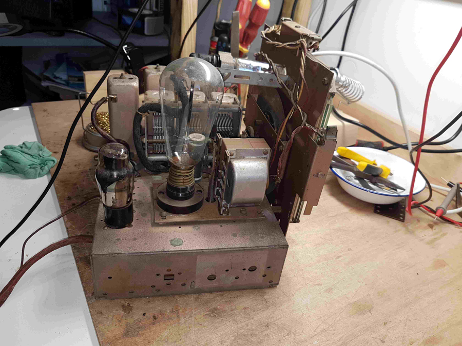
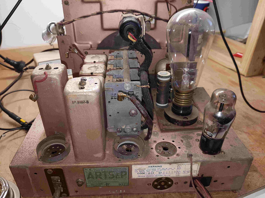
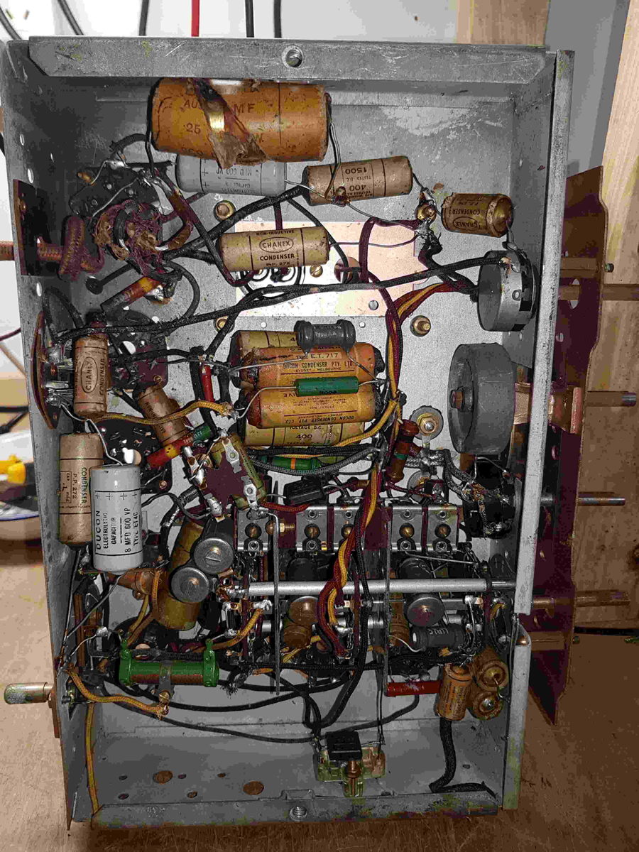
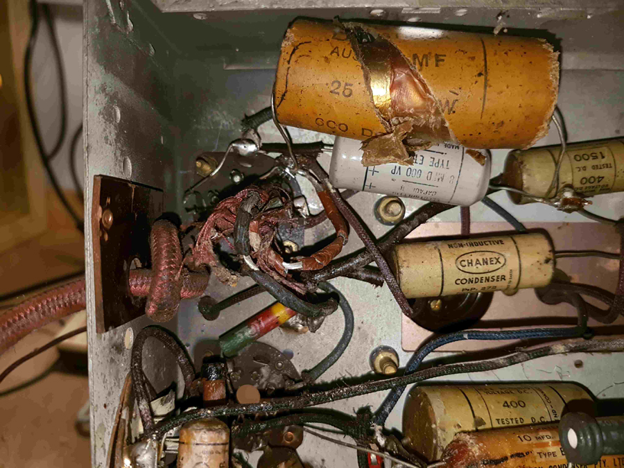
 Return to top of page · Post #: 2 · Written at 7:45:06 PM on 30 August 2018.
STC830's Gravatar
 Location: NSW
 Member since 10 June 2010
 Member #: 681
 Postcount: 1256

Hello Nhanwell

The circuit is not in AORSM.
It is listed in
http://www.hrsa.asn.au/hrsa-files/radio-models.pdf and
http://hws.org.au/RadioHistory/manufacturers/STC.htm
but without a valve lineup.
But looking at models either side

6U7G, 6K8G, 6U7G, 6Q7G, 6AG6G, 5Z4G, 6T5

looks likely.

The 6T5 is quite rare and expensive NOS as it is in demand by contemporary Zenith owners in the USA.
6G5/6U5 is a direct substitute.


 Return to top of page · Post #: 3 · Written at 9:13:07 PM on 30 August 2018.
Nhanwell's Gravatar
 Location: Mount Lawley, WA
 Member since 12 September 2017
 Member #: 2167
 Postcount: 49

Hi STC830

The magic eye has a 6 pin base...manufactured by Brimar UK .. but no visible identifying markings.
From memory, from the very short time it was running, I think it had a more conventional eye pattern and not the distinctive 6T5.

I'll have to try it in another set and see what it looks like.


 Return to top of page · Post #: 4 · Written at 8:48:41 AM on 31 August 2018.
STC830's Gravatar
 Location: NSW
 Member since 10 June 2010
 Member #: 681
 Postcount: 1256

One thing to look out for is that there can be a 1Mohm resistor in the socket of these old indicator valves which will likely be high.

Radiomuseum website indicates that there is an 633R and a 633K and that the K has a record player. So that might make yours a 633R. The source of the information is given as

Radio and Electrical Retailer, Australia (2/6/39) and also in
Mingay's Radio & IF Index.

I can't help you with those but I can send a circuits of the 634 and 635, 1940-41 radios that have the same valve line-up. The 632 has the same lineup without the indicator valve.

I have dug up a photo of the the 633 chassis that I downloaded off the net when for sale, when researching my 632. The chassis is shallow in depth like the 632, but wider.


 Return to top of page · Post #: 5 · Written at 10:34:38 AM on 31 August 2018.
Nhanwell's Gravatar
 Location: Mount Lawley, WA
 Member since 12 September 2017
 Member #: 2167
 Postcount: 49

I've had a good look at the magic eye this morning. Its most likely a 6T5. The face doesn't look at all like a 6U5. No "horizontal" line across the target.
I have the AORSM volumes 3 & 4 in my collection thanks. I've uploaded the 635 circuit diagram to RadioMuseum this morning along with suggested changes to 633 to reflect valve line up.


 Return to top of page · Post #: 6 · Written at 9:01:08 PM on 2 September 2018.
Nhanwell's Gravatar
 Location: Mount Lawley, WA
 Member since 12 September 2017
 Member #: 2167
 Postcount: 49

A very productive weekend .. rewired the set back to parallel heater chain, replaced all the wax capacitors - not a single one measured close to spec and more than 80% were (very) leaky. All the resistors were within tolerance! . Amazing how much more stable resistors from 1939 are compared to those from the mid 30's. A credit to improved techniques in just a few years.

I transplanted a donor mains transformer and HT smoothing choke and tone control pot with mains switch.

I usually bring back the set in stages - just in case I've stuffed up. First with no valves .. check voltages. Then install rectifier check voltages, then install Output & AF amplifier valves - quick check that touching the top cap of 6Q7G generates a loud raspberry in the speaker.
Then put the remaining valves in. Without shields/caps there was a motor-boating..but once the valve shields/caps were installed ..perfectly stable - and immediately the set sprang to life .. even without an antenna there was plenty of volume noise free from all the metro stations.

As an AC/DC set the 6AG6G output valve had been replaced by a 25A6G.
I fired the set up using a 6V6G as I couldn't find a 6AG6G amongst my spares in the attic.
I'm now wondering what to use as a substitute for the 6AG6 - or whether it will make much difference. The output transformer is marked 10,000 ohms.
I have a several spare 6V6G & 6F6G valves.
I am right in thinking that I could use either valve ? I just need to reduce the value of the cathode bias resistor - which is currently 500 ohms to ~ 250 ohms?

Oh by the way - the magic eye is definitely a 6T5 which has a distinctive circular pattern. Another pleasant surprise .. it was still bright enough to see in a lit room!!


 Return to top of page · Post #: 7 · Written at 9:27:29 PM on 2 September 2018.
GTC's avatar
 GTC
 Location: Sydney, NSW
 Member since 28 January 2011
 Member #: 823
 Postcount: 6686

Another pleasant surprise .. it was still bright enough to see in a lit room

Definitely a bonus. Good resto!


 Return to top of page · Post #: 8 · Written at 10:19:00 PM on 2 September 2018.
Marcc's avatar
 Location: Wangaratta, VIC
 Member since 21 February 2009
 Member #: 438
 Postcount: 5252

Wrong thought! .250V plate 6AG6 draws around 38mA plate plus screen; grid 1 -6V. 6V6 plate plus screen at max 52mA; grid1 -12.5V.

So there is a risk of straining a few friendships, like the transformer. you will need about -15V grid to hold back a 6V6 to 38mA so you may need closer to Rk at 470 Ohms. The voltage across Rk will give the current. Cutting back the 6V6 may give a voltage rise?

Wax paper caps leaking badly is of no surprise. Still no feedback from SC If leak is below 200Meg for a coupling cap its a fail. If its me, if it leaks at all its a fail. Leaking coupling caps wreak havoc on bias.


 Return to top of page · Post #: 9 · Written at 7:12:19 AM on 3 September 2018.
STC830's Gravatar
 Location: NSW
 Member since 10 June 2010
 Member #: 681
 Postcount: 1256

"Another pleasant surprise .. it was still bright enough to see in a lit room"

These monster consoles tended to be retired out of the lounge room when TV came in. My 830 was in the late '60s. This might account for 6T5s still retaining a bit of life.


 Return to top of page · Post #: 10 · Written at 4:17:43 PM on 4 September 2018.
Nhanwell's Gravatar
 Location: Mount Lawley, WA
 Member since 12 September 2017
 Member #: 2167
 Postcount: 49

Thanks Marc, always appreciate your comments.

For some reason the cathode resistor was a 500 ohm wirewound - not 150 ohm which STC used on most models with a 6AG6G.
The voltage across it measures ~12v which equates to a quiescent current of 24mA.

A few other things I picked up was that the electro-dynamic speaker had been replaced with a permanent magnet one.
I assuming the voltage drop across the field coil would have been an issue when trying to run the set off 220v DC - which was the mains voltage in the area this set came from.

I used the HT choke (~500 ohms) which was part of the conversion and a 10w dropper of ~ 1600 ohms (2x3K3 in parallel) which gives me an HT of 275v and ~260 v on the anode of the output valve. Unfortunately, all the STC circuit diagrams I have managed to found are devoid of voltages. I'm assuming the above should be fairly close.


 Return to top of page · Post #: 11 · Written at 7:36:46 AM on 5 September 2018.
Fred Lever's Gravatar
 Location: Toongabbie, NSW
 Member since 19 November 2015
 Member #: 1828
 Postcount: 1250

Nigel, thanks for the original photos!

I love how gung ho we were back then.
The mains soldered straight to the chassis? That should be safe!!!!
Yeh I know it was in a DC set up but your blood freezes when you think of a 2nd owner just plugging into the new fangled AC mains update!I
Then grabbing a bare pot shaft!

I want to make a set with one of those giant balloon tube things!
I could make a feature of thing and mount it on the top of the cabinet like an "uncle Fester" decoration.

Nice under chassis shots, looks ready to go just like it is, tho you might need some gaffer tape on that big capacitor to keep the smoke in.
Just kidding.
Fred.


 Return to top of page · Post #: 12 · Written at 9:49:16 AM on 5 September 2018.
Marcc's avatar
 Location: Wangaratta, VIC
 Member since 21 February 2009
 Member #: 438
 Postcount: 5252

It could be that someone was savvy to the ramifications of changing to 6V6 and did it. The lower ohm Rk was probably right for the original valve.

We used a lot of transformer sets and we actually had the foresight to use taps to cater for the pre-grid variations in voltage, from a multitude of generating sites. The most common "B" Voltage was 250. If you look at the Valve specs like 6V6 Rk is a clue as is the total current through a back-bias as the OP valve grid is often on the CT and the drop across R bias train CT to ground is the bias of the OP Valve.

NB.For young players. With Philips & some others. If there is an electrolytic cap of around 40V 25μF across the Back-bias; CT is the most negative and the positive goes to ground: Negative to CT.

If all else fails with a hot chassis set an off / on set transformer, or where you cannot get the Barretter. An LR8 shunting a TIP50 is popular with the Americans. (5V to 400V) Note STC chassis & Model may not be the same chassis 59 is almost impossible to find data on. An external antenna on a hot set should have a 0.01mfd "line cap" in series with it (cap inside).


 Return to top of page · Post #: 13 · Written at 10:08:07 AM on 5 September 2018.
Nhanwell's Gravatar
 Location: Mount Lawley, WA
 Member since 12 September 2017
 Member #: 2167
 Postcount: 49

Thanks Fred.
The STC set is certainly well engineered, far from basic. The edge lit dials work incredibly well ..two different glasses - one for BC and the other for SW & "MW" (what came to be known as tropical band - 115 - 40 m).

The big balloon thing was identified as a 302 Barreter. Its huge with an Edison screw base. I'd only come across the more cylindrical looking barreters with P type base before.

Last night I was going through "Australian Radio Trade Annuals" for 1938 & 1939..amongst other things they list "Electricity Supply Voltages Throughout Australia. Interestingly in 1938 there was not a single town in Western Australia more than 30 Km from Perth (250v 40c) which had AC mains. The majority were 220v DC .. Kalgoorlie was an exception it had 220v DC & 110v 40c (influence of mining industry).

In 1939 there were a few towns (notably Albany on the south coast) which had changed to AC 250v 50c.

A very different situation to Eastern Australia where AC mains were much more widespread.
Probably explains why I seem to have so many pre-war AC/DC sets in my attic awaiting attention Sad.


 Return to top of page · Post #: 14 · Written at 6:39:32 AM on 8 September 2018.
Wa2ise's avatar
 Location: Oradell, US
 Member since 2 April 2010
 Member #: 643
 Postcount: 830

QUOTE: "The first problem was the one of safety when the particular house was fed with a negative outer pole. As described concerning the broadcast receivers, if the valve circuitry was then operated direct from the DC mains, the negative rail had to be isolated from ground and any part of the metal housing connected to ground.

The second problem concerned supply for valve heaters. On AC mains, a step down transformer was normally used, but on DC this option was not available", from https://www.qsl.net/vk5br/Operation_on_DC_Mains.htm


Well, borrowing from today's technology, one could build a vacuum tube version of a switching power supply. A power tube or two, and another tube as the oscillator and some form of voltage regulation via a feedback loop. TV sets did something like this with the horizontal output, using portions of that to generate the very high voltage for the picture tube, and some boosted B+. On the "cold" side, maybe use filament tubes to reduce power demands off this switching power supply. (heater-cathode insulation isn't good enough to isolate the powerline/mains from a cold chassis). Or figure you can get away with your chassis being tied to your electrical ground (that happens to be positive) and use a series heater string. And you might be able to connect your RF output stage tube directly to the negative hot line (if you're careful), using an RF coupling transformer to get from the "cold" oscillator and modulator circuits to the "hot" RF output tube. The hot negative line would be the "ground" for this tube. And then another RF coupling transformer or cap to feed the antenna. The heater of the RF output tube(s) could be connected to the other end of the series heater string for the tubes of the "cold" circuits (which get their B+ from the switching power supply).

Hot negative 220VDC------^--^----dropping resistor----^--^--^--^----positive ground
............. heaters of: ... RF output ...................... cold oscillator and such

The switching power supply ^ heaters could also be adjacent to the RF output tube heater.


 Return to top of page · Post #: 15 · Written at 9:37:54 AM on 8 September 2018.
Marcc's avatar
 Location: Wangaratta, VIC
 Member since 21 February 2009
 Member #: 438
 Postcount: 5252

One must exercise caution with tube sets & switch mode power supplies. I have had them get into the IF & are generally worse than the vibrator type to clean. I also noted on a Guitar Amp.(100W RMS solid state) with one, that if any cable was run near the back of it; that cable would fall foul of the Switch mode PSU

When I donated it to a rural school group, the instructions re microphones, especially the module for the cordless one carried the warning on running wires behind it.


« Back · 1 · 2 · Next »
 You need to be a member to post comments on this forum.

Sign In

Username:
Password:
 Keep me logged in.
Do not tick box on a computer with public access.