
Tech Talk
Forum home - Go back to Tech talk
|
Possible Lekmek Kit set ~ 1933
|
|
|
« Back ·
1 ·
Next »
|
|
|
Return to top of page · Post #: 1 · Written at 6:27:55 PM on 14 August 2018.
|
|
|
|
Location: Mount Lawley, WA
Member since 12 September 2017 Member #: 2167 Postcount: 49 |
|
I acquired this set over 20 years ago now and its been sitting in the corner awaiting some attention. 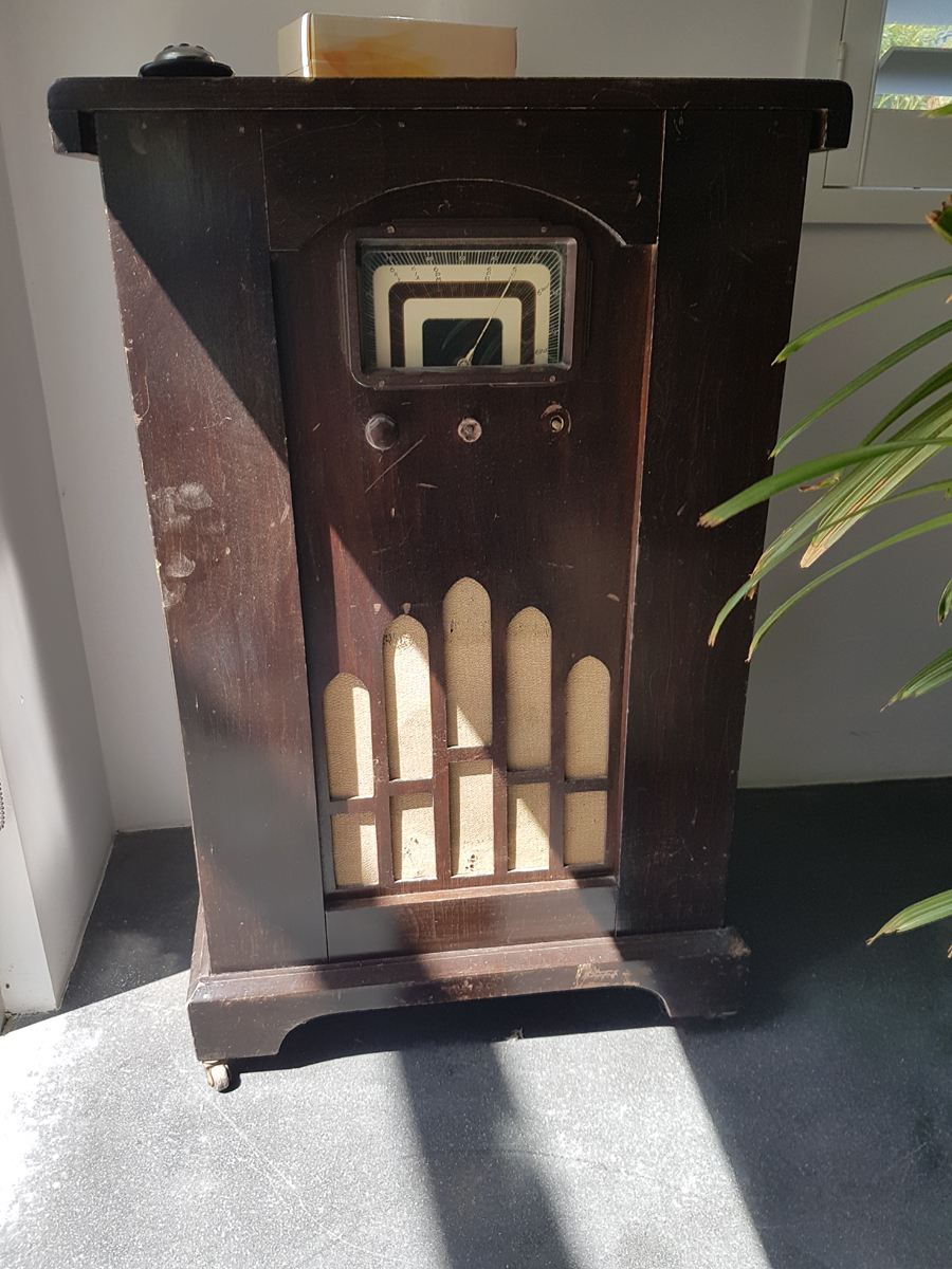  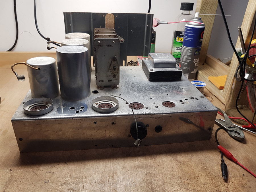 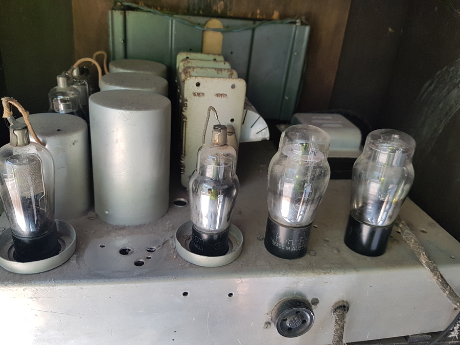 |
|
|
Return to top of page · Post #: 2 · Written at 10:21:40 PM on 14 August 2018.
|
|

|
Location: Wangaratta, VIC
Member since 21 February 2009 Member #: 438 Postcount: 5715 |
|
One may have to make an attempt to reverse engineer it. 75; 42; 80 was a fairly common audio end for a lot of radios. |
|
|
Return to top of page · Post #: 3 · Written at 5:47:34 AM on 16 August 2018.
|
|

|
Administrator
Location: Naremburn, NSW
Member since 15 November 2005 Member #: 1 Postcount: 7624 |
|
Photos uploaded. ‾‾‾‾‾‾‾‾‾‾‾‾‾‾‾‾‾‾‾‾‾‾‾‾‾‾‾‾‾‾‾‾‾‾‾‾‾‾‾‾‾‾‾‾‾‾‾‾‾‾‾‾‾‾‾‾‾‾‾‾‾‾‾‾‾‾‾‾ A valve a day keeps the transistor away... |
|
|
Return to top of page · Post #: 4 · Written at 1:44:51 PM on 16 August 2018.
|
|
|
|
Location: Mount Lawley, WA
Member since 12 September 2017 Member #: 2167 Postcount: 49 |
|
Thanks Marc |
|
|
Return to top of page · Post #: 5 · Written at 9:05:38 PM on 16 August 2018.
|
|
|
|
Location: Wangaratta, VIC
Member since 21 February 2009 Member #: 438 Postcount: 5715 |
|
Surprised its not nitro-cellulose finish at that age. I normally draw the layout, transformers, valves etc initially with an AutoCad & then print it then play join the dots using different colours, or its if it has one? |
|
|
Return to top of page · Post #: 6 · Written at 11:46:05 AM on 17 August 2018.
|
|
|
|
Location: Toongabbie, NSW
Member since 19 November 2015 Member #: 1828 Postcount: 1407 |
|
Hi Nigel, what was sitting between the 2 valves at the left to create the round brighter patch? |
|
|
Return to top of page · Post #: 7 · Written at 3:43:15 PM on 17 August 2018.
|
|
|
|
Location: Mount Lawley, WA
Member since 12 September 2017 Member #: 2167 Postcount: 49 |
|
It was the 2nd IF transformer. |
|
|
Return to top of page · Post #: 8 · Written at 5:44:39 PM on 17 August 2018.
|
|
|
|
Location: Toongabbie, NSW
Member since 19 November 2015 Member #: 1828 Postcount: 1407 |
|
Well done Nigel, if the IF works and the set is sensitive, leave it. |
|
|
Return to top of page · Post #: 9 · Written at 6:29:17 PM on 17 August 2018.
|
|

|
Location: Sydney, NSW
Member since 28 January 2011 Member #: 823 Postcount: 6949 |
|
Well done Nigel |
|
|
Return to top of page · Post #: 10 · Written at 12:22:55 AM on 18 August 2018.
|
|
|
|
Location: Wangaratta, VIC
Member since 21 February 2009 Member #: 438 Postcount: 5715 |
|
I would like to be that lucky at the moment. I have a Grigsby- Grunow that has two destroyed IFT's (175kHz) and I have now noted that the Monarch (one of 3 sets in work) had a 100k resistor to V1 plate as the primary of the coil between it & V2 is open & its not by the looks of it an external break on a coil, or node. |
|
|
Return to top of page · Post #: 11 · Written at 5:24:45 PM on 19 August 2018.
|
|
|
|
Location: Mount Lawley, WA
Member since 12 September 2017 Member #: 2167 Postcount: 49 |
|
Thanks guys. 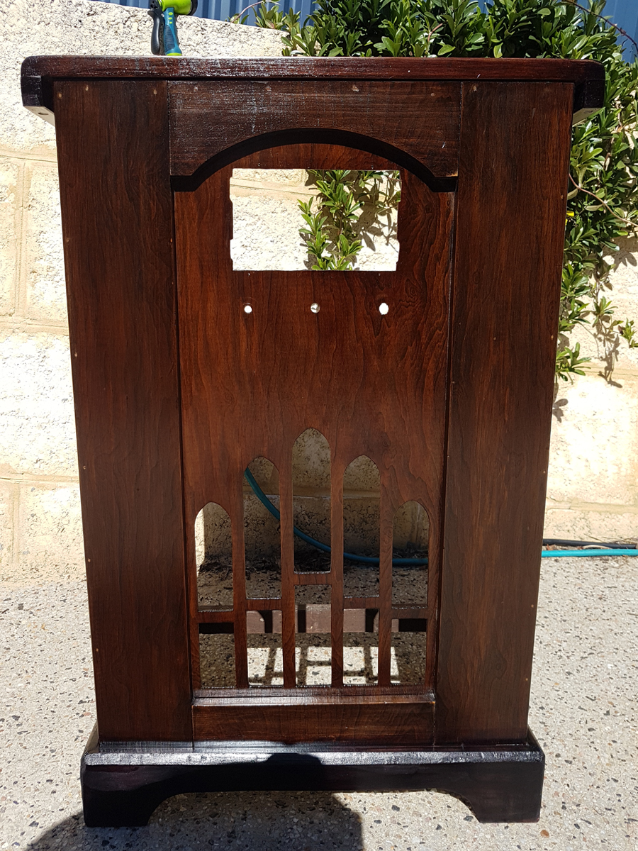 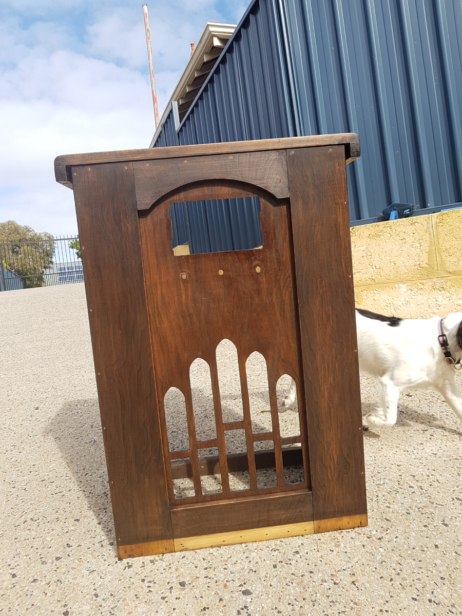 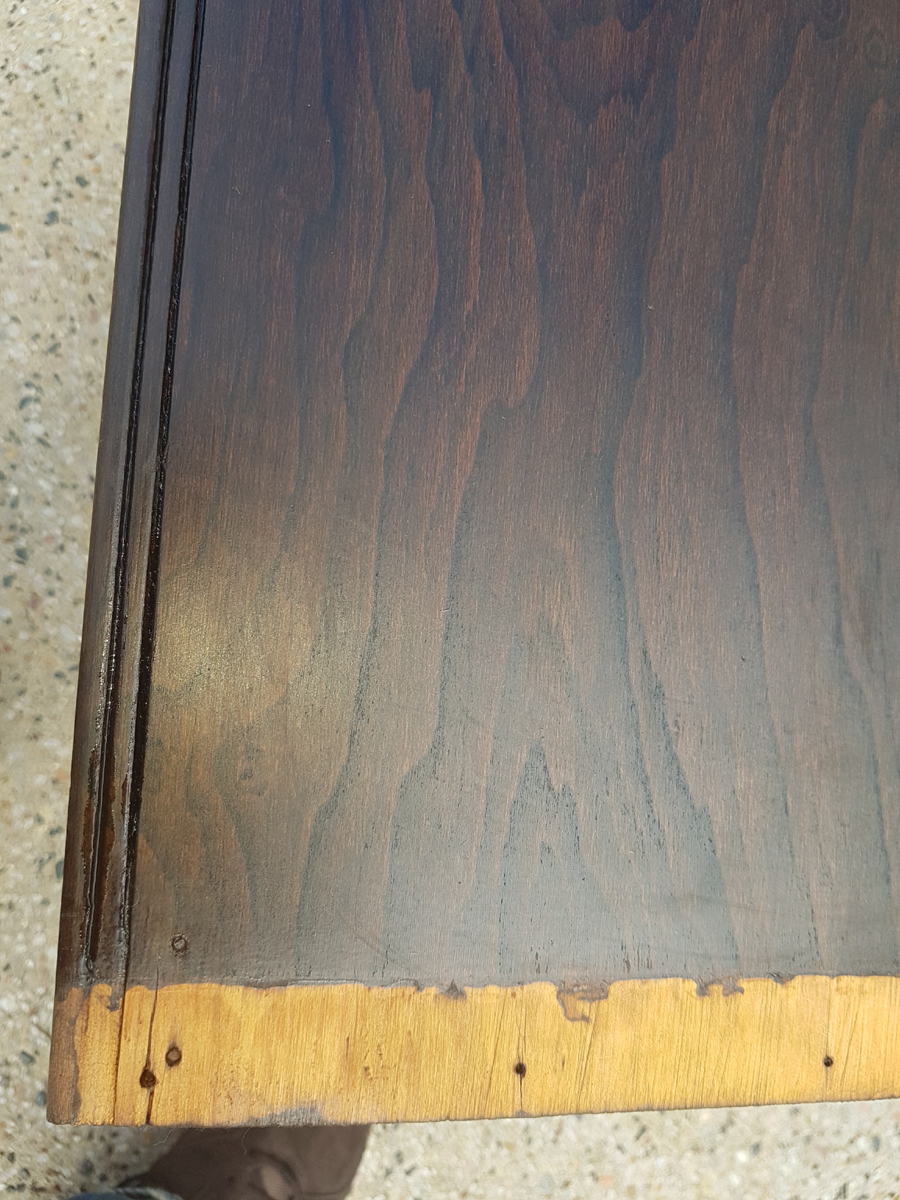 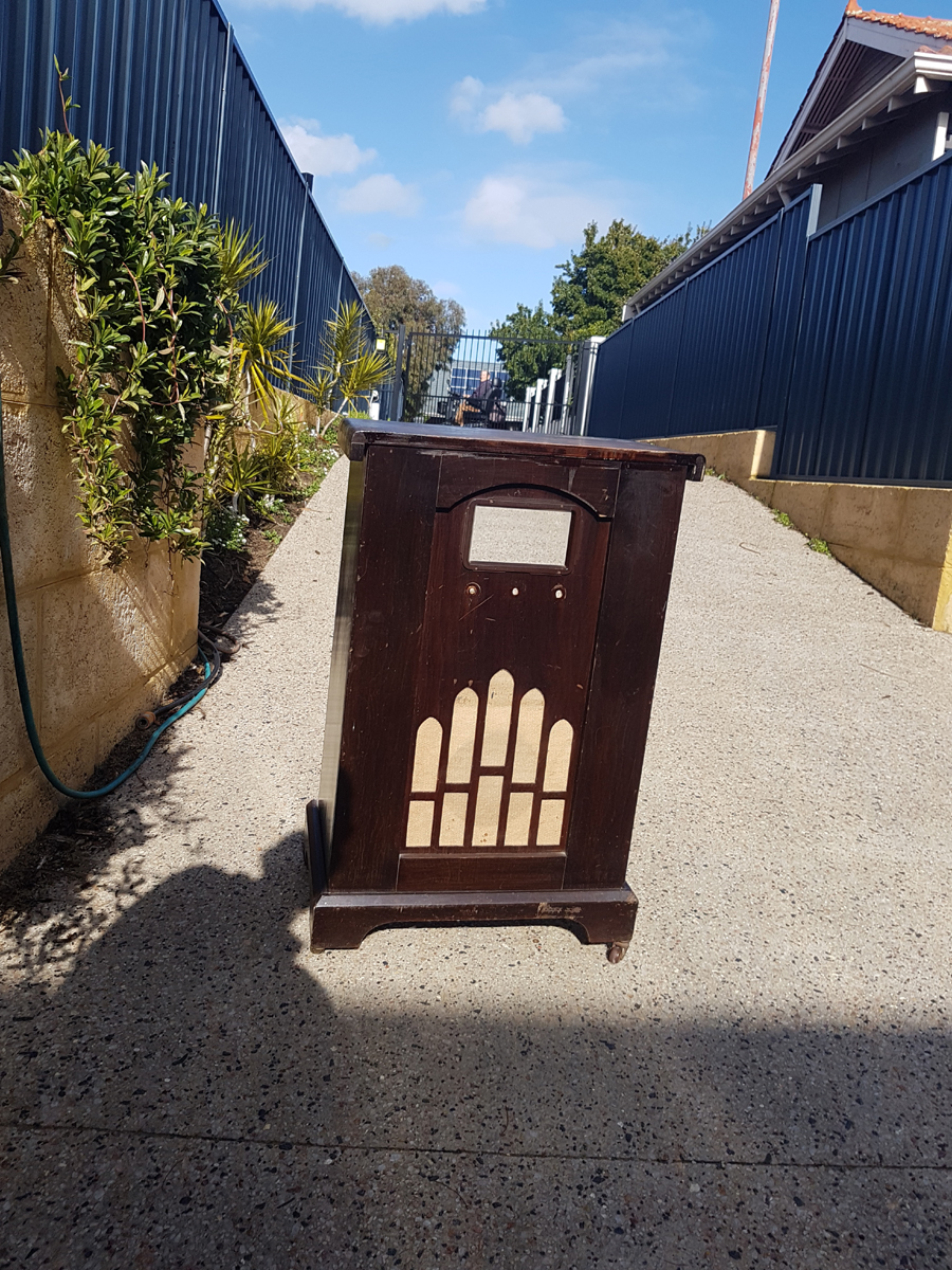 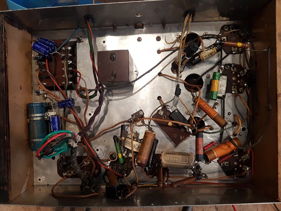 |
|
|
Return to top of page · Post #: 12 · Written at 9:53:30 PM on 19 August 2018.
|
|
|
|
Administrator
Location: Naremburn, NSW
Member since 15 November 2005 Member #: 1 Postcount: 7624 |
|
Photos uploaded to Post 11. ‾‾‾‾‾‾‾‾‾‾‾‾‾‾‾‾‾‾‾‾‾‾‾‾‾‾‾‾‾‾‾‾‾‾‾‾‾‾‾‾‾‾‾‾‾‾‾‾‾‾‾‾‾‾‾‾‾‾‾‾‾‾‾‾‾‾‾‾ A valve a day keeps the transistor away... |
|
|
Return to top of page · Post #: 13 · Written at 9:21:34 AM on 20 August 2018.
|
|
|
|
Location: Wangaratta, VIC
Member since 21 February 2009 Member #: 438 Postcount: 5715 |
|
I would monitor the start up surge, whilst that has a divider which may pull down the surge, in many sets with #80 / 5Y3 and those that behave in a similar fashion, that surge can get to, or exceed 500V. |
|
|
Return to top of page · Post #: 14 · Written at 1:04:15 PM on 20 August 2018.
|
|
|
|
Location: Toongabbie, NSW
Member since 19 November 2015 Member #: 1828 Postcount: 1407 |
|
Thanks for shot of underside, I love looking at old stuff. I guess by now all the carbon resistors, paper caps have been changed, plus those sub miniature blue electros! Those little caps have their place but not in a chassis where the HT heads for blue sky on power up. As Ian says the HT can go 600v plus for seconds before the output valve draws current. I have used the little blue caps in some repairs but put two in series and in critical places put 1m sharing resistors across them. Most of my repairs have reformed used can caps or reformed old stock large diameter units and only put in after bench testing for leakage and heat rise. |
|
|
Return to top of page · Post #: 15 · Written at 3:47:13 PM on 26 August 2018.
|
|

|
Location: Beechmont, QLD
Member since 10 April 2009 Member #: 465 Postcount: 109 |
|
|
|
|
« Back ·
1 ·
Next »
|
|
|
You need to be a member to post comments on this forum.
|
|
Sign In
Vintage Radio and Television is proudly brought to you by an era where things were built with pride and made to last.
DISCLAIMER: Valve radios and televisions contain voltages that can deliver lethal shocks. You should not attempt to work on a valve radio or other electrical appliances unless you know exactly what you are doing and have gained some experience with electronics and working around high voltages. The owner, administrators and staff of Vintage Radio & Television will accept no liability for any damage, injury or loss of life that comes as a result of your use or mis-use of information on this website. Please read our Safety Warning before using this website.
WARNING: Under no circumstances should you ever apply power to a vintage radio, television or other electrical appliance you have acquired without first having it checked and serviced by an experienced person. Also, at no time should any appliance be connected to an electricity supply if the power cord is damaged. If in doubt, do not apply power.
Shintara - Keepin' It Real · VileSilencer - Maintain The Rage