Welcome to Australia's only Vintage Radio and Television discussion forums. You are not logged in. Please log in below, apply for an account or retrieve your password.
Australian Vintage Radio Forums
  Home  ·  About Us  ·  Discussion Forums  ·  Glossary  ·  Outside Links  ·  Policies  ·  Services Directory  ·  Safety Warnings  ·  Tutorials

Tech Talk

Forum home - Go back to Tech talk

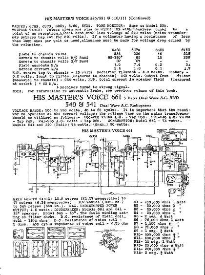
 HMV 1941 Model 661
« Back · 1 · 2 · 3 · Next »
 Return to top of page · Post #: 1 · Written at 10:18:32 PM on 4 January 2010.
VK6XT's Gravatar
 Location: BromeHill, WA
 Member since 3 September 2009
 Member #: 542
 Postcount: 14

Hi everyone...Happy New Year.
I wonder if anybody has the circuit for this beast. It is a Dual wave set
featuring in AORSM '40/41 Pg 155 (apparently). I also see a reference to HRSA 1/93 . Set starts out OK but fades away to nothing after an Hour or so.

Rick.


 Return to top of page · Post #: 2 · Written at 12:12:35 AM on 5 January 2010.
Marcc's avatar
 Location: Wangaratta, VIC
 Member since 21 February 2009
 Member #: 438
 Postcount: 5254

Rick, welcome to a nightmare.

I have a circuit for that one and have repaired one in the last two years.

A large number of the resistances were out of spec. and as normal all paper caps & electrolytics had had to go. As you will know, or are about to find out, the components are on about seven boards, in a "U" shaped tunnel formed by the central Faraday cage around the switches. the components in there are awkward but gettable.

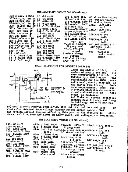
They also modified during the war & changed to EBF2G, the circuit was modified to suit & the one I had, was one of them.

Take photo's before you start & be prepared to have to remove the boards one by one (to make a good job), rather than try and get at them in situe.

Be seriously aware that the filter caps are a trap; use 500V types or bigger. The speaker field is in the earth lead, therefore the negatives are each side of the field & both positives are common. I fitted terminal strips & mounted them in the tunnel.

If yours has old paper caps I would tend to get rid of them, check resistors & replace all of the electrolytics, then look for the fault if its still there. The fact that it is fading is of concern as it could indicate heating or severe leakage.

I would strongly suggest that you follow what I did with the 661 I fixed & use the Russian type (Sovtek I think) which has a very high thermal inertia filament. This will heat slowly & takes a lot of stress of of the components. The 661 had a fairly savage surge voltage this will cut it down. (5Y3 was faulty)

As usual HMV went to a lot of trouble to decouple everything, so its a performance is on par with the quality.

Marc


 Return to top of page · Post #: 3 · Written at 2:48:50 PM on 5 January 2010.
VK6XT's Gravatar
 Location: BromeHill, WA
 Member since 3 September 2009
 Member #: 542
 Postcount: 14

Hi Marc,
Thanks for the Reply. My radio has the EBF2G fitted.... It is going to be replaced with a 6B8G shortly. I have really got to the stage where I need a circuit diagram to check voltages and component values. Some one had fitted an EK2G in place of the 6J8G (surely not HMV?) ..it worked Slightly !! and all seemed promising when I changed that one .
Would really appreciate a copy of the circuit....I will pay for any expenses incurred. I think my eMail is visible in my Profile.


 Return to top of page · Post #: 4 · Written at 6:26:28 PM on 5 January 2010.
Brad's avatar
 Administrator
 Location: Naremburn, NSW
 Member since 15 November 2005
 Member #: 1
 Postcount: 7301

G'day Rick,

Unfortunately at this stage the e-mail addresses in member profiles are only visible to the member that owns it. It is a security feature to help with preventing your e-mail addresses being scanned by hostile web crawler robots and then spammed.

At this stage members can choose to place their e-mail address in their posts and there is a feature that comes with this ability that helps prevent the e-mail address 'looking' like one to a web crawler robot but I cannot guarantee perfect success so I leave it up to members to make this decision.

In the future I will make a slight change to member profiles to allow members the choice of whether they would like to display an e-mail address for the convenience of other members. Hopefully there will be time to implement this soon.

It is unfortunate that security has to be a paramount consideration though this is a problem that exists on all discussion forums and it is really a case of when finding a way to beat these robots the robot developers discover the tricks and then find ways to circumvent them. It is like the radar detector industry (in states that still allow them to be used) where a company will offer drivers a better radar detector and then offer the police force a radar unit that can circumvent the latest detectors.


‾‾‾‾‾‾‾‾‾‾‾‾‾‾‾‾‾‾‾‾‾‾‾‾‾‾‾‾‾‾‾‾‾‾‾‾‾‾‾‾‾‾‾‾‾‾‾‾‾‾‾‾‾‾‾‾‾‾‾‾‾‾‾‾‾‾‾‾
A valve a day keeps the transistor away...

 
 Return to top of page · Post #: 5 · Written at 10:30:33 PM on 5 January 2010.
Marcc's avatar
 Location: Wangaratta, VIC
 Member since 21 February 2009
 Member #: 438
 Postcount: 5254

Rick

EBF2G (not interchangeable with EBF2) Is not directly pin interchangeable with either 6B8G or 6J8: EBF35 is.

The heater pinouts are different. 6J8 & 6B8 follow the more common IO convention of heaters pins 2& 7. EBF2G follows the convention similar to the old valves. Its heaters are 1& 8

Do get the valve pinouts before changing things. EBF2G is a remote cut off RF Penode dual diode, 6B8 is a Medium cut off RF Pentode dual diode. Thats the other reason the circuit has to be changed, or it will all go "pear shaped".

Only the "Monkeys" would have put the EBF2G where the 6J8 should be its a Triode Heptode. That sort of thing can do serious damage to the set and/or the valve. I can't remember if the chassis on that was labelled, but from memory the 6J8's base is in the Faraday cage.

I have photo's filed somewhere, but the set is only about 10Km from me if one needs to check. The circuitry is a dead giveaway all the RF coils attach to 6J8 via the switch and its grid cap will go to the tuning gang.

Marc


 Return to top of page · Post #: 6 · Written at 10:35:06 PM on 5 January 2010.
Marcc's avatar
 Location: Wangaratta, VIC
 Member since 21 February 2009
 Member #: 438
 Postcount: 5254

Forgot

Emailed circuit to Brad.

Clarification: Replace 5Y3 with Russian 5Y3 (see previous for why)


Click on images to view higher resolution.


 Return to top of page · Post #: 7 · Written at 11:04:53 PM on 5 January 2010.
VK6XT's Gravatar
 Location: BromeHill, WA
 Member since 3 September 2009
 Member #: 542
 Postcount: 14

OK Marc,
Thanks for all the info.. I pulled the EBF2G and checked ....yes the filament is across 1 and 8. I had looked up the pinout on "Franks " pages, I think he had the EBF2G and the EBF35 shown together. I am getting a little bit familiar with the Phillips P-base tubes as well... another set I am working on is The Phillips 6506...1934 model.
Back to the HMV though. It was an EK2G in the front end instead of the 6J8... !! 6J8 Is at the front just to the Right of the Faraday cage. I hold off on the conversion of the EBF2G until I find the Problem..it is in the front end anyway...have got audio gain past the volume pot.
Best Regards, Rick


 Return to top of page · Post #: 8 · Written at 2:12:33 AM on 6 January 2010.
Marcc's avatar
 Location: Wangaratta, VIC
 Member since 21 February 2009
 Member #: 438
 Postcount: 5254

Rick

The other tube used instead of the philips was 6K7 and I have seen often a 6U7 in sets that use 6K7, it should actually work. if the grid bias is set for -3V

If you check the socket heater pinouts, that will tell you which one it should have as 6U7 & 6K7 have heaters 2&7 not 1 & 8

The oscillator plate of 6J8 is decoupled (pin6) with a paper & an electrolytic cap. either one failing / leaking will kill it. Also check the screen divider. 6J8 likes lots of volts on the plate.

Marc


 Return to top of page · Post #: 9 · Written at 9:09:10 PM on 6 January 2010.
Brad's avatar
 Administrator
 Location: Naremburn, NSW
 Member since 15 November 2005
 Member #: 1
 Postcount: 7301

Images are up gentlemen. Sorry about the delay. Wink


‾‾‾‾‾‾‾‾‾‾‾‾‾‾‾‾‾‾‾‾‾‾‾‾‾‾‾‾‾‾‾‾‾‾‾‾‾‾‾‾‾‾‾‾‾‾‾‾‾‾‾‾‾‾‾‾‾‾‾‾‾‾‾‾‾‾‾‾
A valve a day keeps the transistor away...

 
 Return to top of page · Post #: 10 · Written at 11:13:41 PM on 6 January 2010.
Marcc's avatar
 Location: Wangaratta, VIC
 Member since 21 February 2009
 Member #: 438
 Postcount: 5254

Brad,

Thanks, circuit will clarify, for others, where we are going.

Marc


 Return to top of page · Post #: 11 · Written at 11:54:37 PM on 6 January 2010.
VK6XT's Gravatar
 Location: BromeHill, WA
 Member since 3 September 2009
 Member #: 542
 Postcount: 14

Thanks Gentlemen,
Looks like tomorrow is planned out!
Rick.


 Return to top of page · Post #: 12 · Written at 10:02:51 PM on 7 January 2010.
VK6XT's Gravatar
 Location: BromeHill, WA
 Member since 3 September 2009
 Member #: 542
 Postcount: 14

Found that the HT is being pulled down to 140v by the 6V6. Suspect audio coupling cap to grid or cathode cap . It is driving me crazy so will put it aside for a few days.


 Return to top of page · Post #: 13 · Written at 11:14:10 PM on 8 January 2010.
Marcc's avatar
 Location: Wangaratta, VIC
 Member since 21 February 2009
 Member #: 438
 Postcount: 5254

The 6V6 may be internaly shorted, that is not uncommon. Also use a multimeter to check that pin 8 has no contact with pins 2 & 7

The cathode resistor may be open and has punched through the bypass cap.?

Life will be a lot less frustrating if you go back to my original plan & I have been fixing these things for over 40 years (around 200 in the last couple).

Go over every board, check resistors as you go and replace every paper & electrolytic cap in it. If you free an end of a Mica cap. check it too, prefferably with a megger at 500V.

With an average radio I would say 4 to 5 hrs. That thing may take a long day, perhaps two; as you will have at least one mod. to the filters and plenty of work If you need to remove boards (mark wires & photograph before attacking)

It may not be as much fun ( for me its cost related efficiency) but it will be a more efficient method time wise, of getting it sorted out.

Pardon me if that sounds ruthless but experience says with old sets like this. Check the mains, check the valves and if it looks like a good commercial risk, rip out the parts you know will be bad & nine times out of ten, it will fire up with no, or minimal problems, often corrected by adjustment.

Marc


 Return to top of page · Post #: 14 · Written at 11:57:41 PM on 10 January 2010.
VK6XT's Gravatar
 Location: BromeHill, WA
 Member since 3 September 2009
 Member #: 542
 Postcount: 14

Hi Marc,
Still having a break from the radio. I have a full set of caps for it and The Phillips coming in the Mail. I did check the 6V6 for shorts before packing it away. Checked out OK. Not overly impressed by the socket incidentally.The valve is held very loosely .
Rick


 Return to top of page · Post #: 15 · Written at 2:03:22 AM on 11 January 2010.
Marcc's avatar
 Location: Wangaratta, VIC
 Member since 21 February 2009
 Member #: 438
 Postcount: 5254

I would not panic about the socket, they are readily available.

I hope that checking was done with a valve tester? The only thing that an ohmeter will check with any degree of reliability is heater continuity and heater to cathode shorts.

While the philips valve is still gettable; Its a hassle to modify the set and serves no worthwhile purpose, in my book.

I would also have a look at the AC voltages coming out of the transformer.

The 6V6 can pull around 45mA. If the rectifier is gassy, or HT is being pulled down by shorts, severe leakage, or one HT AC phase is missing, then you really are at a severe disadvantage. Half a 5Y3 can fail, I've seen one do it.

Make sure its a 6V6. I have seen 6L6's put in and that (Renode) needs completely different bias. That set does not have the common plate bypass however, if C27 lets go, it will short out the speaker transformer and change the valve loading.

Marc


« Back · 1 · 2 · 3 · Next »
 You need to be a member to post comments on this forum.

Sign In

Username:
Password:
 Keep me logged in.
Do not tick box on a computer with public access.