Welcome to Australia's only Vintage Radio and Television discussion forums. You are not logged in. Please log in below, apply for an account or retrieve your password.
Australian Vintage Radio Forums
  Home  ·  About Us  ·  Discussion Forums  ·  Glossary  ·  Outside Links  ·  Policies  ·  Services Directory  ·  Safety Warnings  ·  Tutorials

Tech Talk

Forum home - Go back to Tech talk

 Healing 501E Irregular Chassis?
« Back · 1 · Next »
 Return to top of page · Post #: 1 · Written at 10:56:54 AM on 4 May 2018.
Captgogo's Gravatar
 Location: Sydney, NSW
 Member since 22 May 2017
 Member #: 2114
 Postcount: 120

I have acquired at a recent the HRSA swap-meet what seems to be a nice and original Healing 501E, which I want to bring up to a safe and good working condition to run in my home office.

The HRSA member who sold it to me suggested it was working well and I have no reason to doubt him.

After changing the 2 core cable, though rather new, I preferred to have a 3 core cable with ground attached to the Chasis.

I inspected under the Chasis and to my surprise most of the original caps were still in place as far as I could see, or at least the vertical canned Electrolytic were still connected. Refer to Pics happy for you input on what definitely needs changing.

On inspection of the Valves, I noted two replacement valves, 6B6G was replaced with 6SQ7GT and 6U7G was replaced with 6K7G. Also in comparison to the Radiomuseum photo of the Chasis the valves were in slightly different places. It also appears like additional electrolytic can holes exist though I do not believe I am missing any.

I will have Brad post the pics of my Chasis (thx Brad) which differs from 501E on Radiomuseum.

As everything looked ok under the Chasis regarding safety, I decided to put my 60W incandescent light in series and see if the radio worked.

The Radio warmed up quickly and my incandescent light hardly lit up, the radio with a short arial worked extremely well, in fact one of the best mantels I have heard.

So as to not do any damaged to it, due all the original caps/resistors in place, I turned it of after 5 mins and was happy this radio would be great for my home office once all checks and necessary parts were replaced, assuming I do not stuff it up.


So I am about to begin replacing Caps and then checking voltages, but before I start, I thought I would ask the experienced community on this great website, what changes should I expect from the original circuit considering the slight change in the Chasis layout, what do the 2 holes mean? and are there different voltages/ components expected from the two replacement valves, what should I look for?
To the best of my limited research the replacement valves seem to be direct equivalent replacements?

Healing 501E Valve Radio


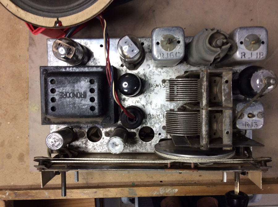
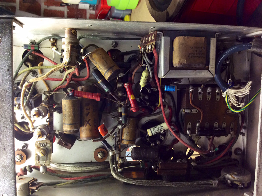
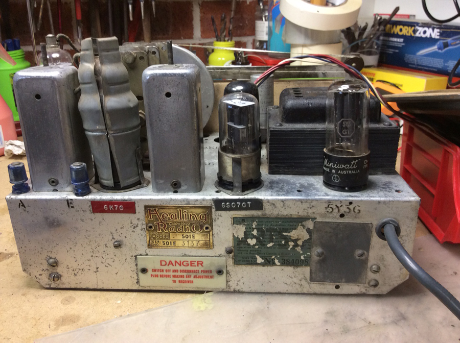
 Return to top of page · Post #: 2 · Written at 2:24:10 PM on 4 May 2018.
Ian Robertson's Gravatar
 Location: Belrose, NSW
 Member since 31 December 2015
 Member #: 1844
 Postcount: 2370

Hey, if it works don't fix it!

The 6SQ7 might have been a factory substitute, it is the single-ended siccessor to the 6B6. The 6K7 from memory is a sharp cut-off rather than a remote cutoff pentode, this might affect the AGC a little but again, if it works leave it alone.

It's quite common for chassis to have unused holes due to changes during a model run.

Maybe the last guy replaced the caps that needed to be replaced and left the others in place. There are some paper caps still around that are not guaranteed to be bad and provided the coupler to G1 of the output valve and any HT bypasses have been changed you're pretty safe.

I expect to get a serve from Marcc about this. I'm not dogmatic about unconditionally replacing all paper caps in radios, I take it on a case-by-case basis and test first based on the type of caps. If I detect one bad cap (I usually do) I'll change all of them. I DO believe in the shotgun approach for TV chassis though.

I have found with TV chassis that it's sometimes possible to slowly re-form existing electros over a week or so. They come up OK, usually but not always.


 Return to top of page · Post #: 3 · Written at 4:32:37 PM on 4 May 2018.
Johnny's avatar
 Location: Hobart, TAS
 Member since 31 July 2016
 Member #: 1959
 Postcount: 544

I also take replacing caps on a case by case basis, however over the 55 odd years of hobby and full time servicing.
Find it is best to only replace faulty(stopping the device from working) parts firstly and then decide whether to replace other parts for both safety or reliability of the repair.
Unfortunately no amount of study or qualifications will tell you to always replace on sight paper caps with two black bands on one end.
And several other components that through experience are alway suspect.
Including going straight for certain resistors in certain locations.
I also try to reform old electros, and have also had a huge success, and can count on one hand the number of electro disasters in a lifetime of not just replacing for the sake of it.
JJ


 Return to top of page · Post #: 4 · Written at 7:39:17 AM on 5 May 2018.
Brad's avatar
 Administrator
 Location: Naremburn, NSW
 Member since 15 November 2005
 Member #: 1
 Postcount: 7301

Photos uploaded.


‾‾‾‾‾‾‾‾‾‾‾‾‾‾‾‾‾‾‾‾‾‾‾‾‾‾‾‾‾‾‾‾‾‾‾‾‾‾‾‾‾‾‾‾‾‾‾‾‾‾‾‾‾‾‾‾‾‾‾‾‾‾‾‾‾‾‾‾
A valve a day keeps the transistor away...

 
 Return to top of page · Post #: 5 · Written at 9:57:25 AM on 5 May 2018.
Ian Robertson's Gravatar
 Location: Belrose, NSW
 Member since 31 December 2015
 Member #: 1844
 Postcount: 2370

Looks like previous owner has replaced the caps that matter with polyesters, The pitch-ended Ducon paper caps were better than the later "High Seal 85"s - they are probably OK.

It ain't broke! Leave it alone!!


 Return to top of page · Post #: 6 · Written at 11:06:34 AM on 5 May 2018.
Captgogo's Gravatar
 Location: Sydney, NSW
 Member since 22 May 2017
 Member #: 2114
 Postcount: 120

Thanks Ian, and Johnny for your input, I tend to follow the same principle for other things "if Ain't Brkoke,Don't mess with it".
But as I am slowly gaining confidence with this type of HV electronics, I have to admit being initially paranoid about Caps exploding and destroying good hard to get components.

I did mention the the large smoothing? electrolytic caps in the cans, I think 8μF and 24μF from memory are still connected, should they not be replaced?

Also the photos does not show it up very well their are a couple of black tar type? Caps cannot read the values showing signs of wear with cracks appearing, should they not be replaced?

I gather you can have a Chassis with a model number like the 501E but find differences in the same Chasis relative to say a pic on Radiomuseum. If you compare my Chasis with the one documented, the Speaker socket is placed where a valve is and visa a Versa.

Are slight variations commonly found for similar labeled Chassis?


 Return to top of page · Post #: 7 · Written at 12:41:37 PM on 5 May 2018.
Ian Robertson's Gravatar
 Location: Belrose, NSW
 Member since 31 December 2015
 Member #: 1844
 Postcount: 2370

Can electros are working OK? No hum? No sign of leakage, white crusty deposit around the terminals?

If not I'd leave them alone.

Those old Ducons look OK to me from the pics. There's nothing there that, if it fails, will cause any damage. But if they worry you and you plan to run the radio 12 hours a day, 7 days a week, change them.


 Return to top of page · Post #: 8 · Written at 10:37:21 PM on 5 May 2018.
Marcc's avatar
 Location: Wangaratta, VIC
 Member since 21 February 2009
 Member #: 438
 Postcount: 5254

Consensus on the American Forum and from what I see regularly, is that those Wax paper caps are a liability and can seriously impinge on the performance of a set and the welfare of the valves. In respect of "Non Polarised caps", I have one standard, as I have done quite a bit of commercial fixing. "If it leaks its a dud"

In radio the reference I have quoted many times, is from Lafayette, from an RC Bridge & cap tester. They claim that under 50meg a cap is unsuitable as a Screen decoupling cap and under 200Meg unsuitable as a coupling cap. We should appreciate that where a control grid draws virtually no current any positive DC leaking from a plate can overwhelm the bias and in several cases, send it positive. Therein lies the problem.

With HV Wax paper types, if I bother to test them, I do this mainly with an Insulation type tester at as close to the working volts as I can get. In several hundred radio's in around a fifty year period, it is rare to find any wax paper caps any where near 5Meg. The bigger the cap the worse it is & figures in hundreds of Kilo ohms, or less are more common. leaking caps draw current, or cause more to be drawn: Often that's not healthy, irrespective of how long the set runs.

Test equipment is even more critical. I have seen an AVO 7x, Peak 200H, Palec VCT's, Ignition & Capacitor testers, Oscilloscopes & Signal Generators ........ All have serious calibration & other issues, wholly due to capacitors that leak.


 Return to top of page · Post #: 9 · Written at 3:19:17 PM on 6 May 2018.
Ian Robertson's Gravatar
 Location: Belrose, NSW
 Member since 31 December 2015
 Member #: 1844
 Postcount: 2370

But the caps that are in a position that will damage anything if they leak have already been changed.

Remaining paper caps if they leak might affect the performance but won't do any damage.


 Return to top of page · Post #: 10 · Written at 10:31:06 PM on 6 May 2018.
Marcc's avatar
 Location: Wangaratta, VIC
 Member since 21 February 2009
 Member #: 438
 Postcount: 5254

You will note that was a general comment. In any radio fix I do, if I know the part is going to affect performance, be it resistor, or capacitor, leaving it there does not, in my book constitute a proper refurbish. In a commercial fix I am not getting payed to do half a job and failures are not good for business.

Marc


 Return to top of page · Post #: 11 · Written at 11:12:54 PM on 6 May 2018.
Captgogo's Gravatar
 Location: Sydney, NSW
 Member since 22 May 2017
 Member #: 2114
 Postcount: 120

Thank Ian and Marc both your comments make sense and understand this is a regular debating point on many sites and articles I have come across .
Up to now on the six radios so far I have restored, I have replaced all of the old electrolytic and paper/wax caps.

On this radio due to its very good operating performance, I have decided to only change the C25 paper cap whose black casing was severely cracked and would have possibly deterioted further.

I will be using this radio everyday and any sign of changes in the performance, I will most likely then replace the responsible components and replace the mounted electrolytic caps.


« Back · 1 · Next »
 You need to be a member to post comments on this forum.

Sign In

Username:
Password:
 Keep me logged in.
Do not tick box on a computer with public access.