Tech Talk
Forum home - Go back to Tech talk
|
Russian radio
|
|
|
Return to top of page · Post #: 1 · Written at 12:02:22 PM on 4 April 2018.
|
|
|
|
Location: Hill Top, NSW
Member since 18 September 2015 Member #: 1801 Postcount: 2193 |
|
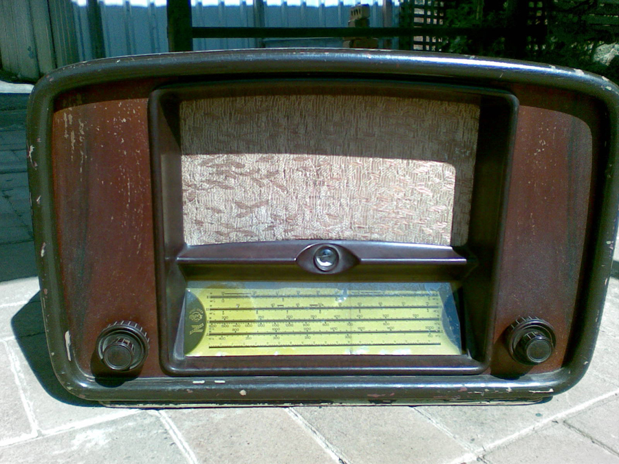
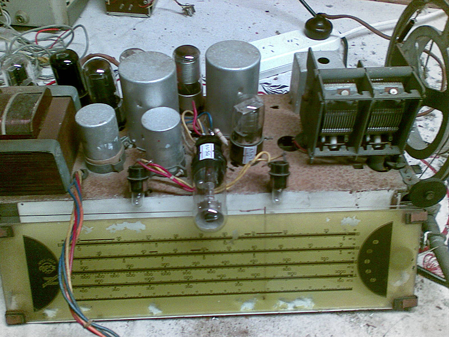
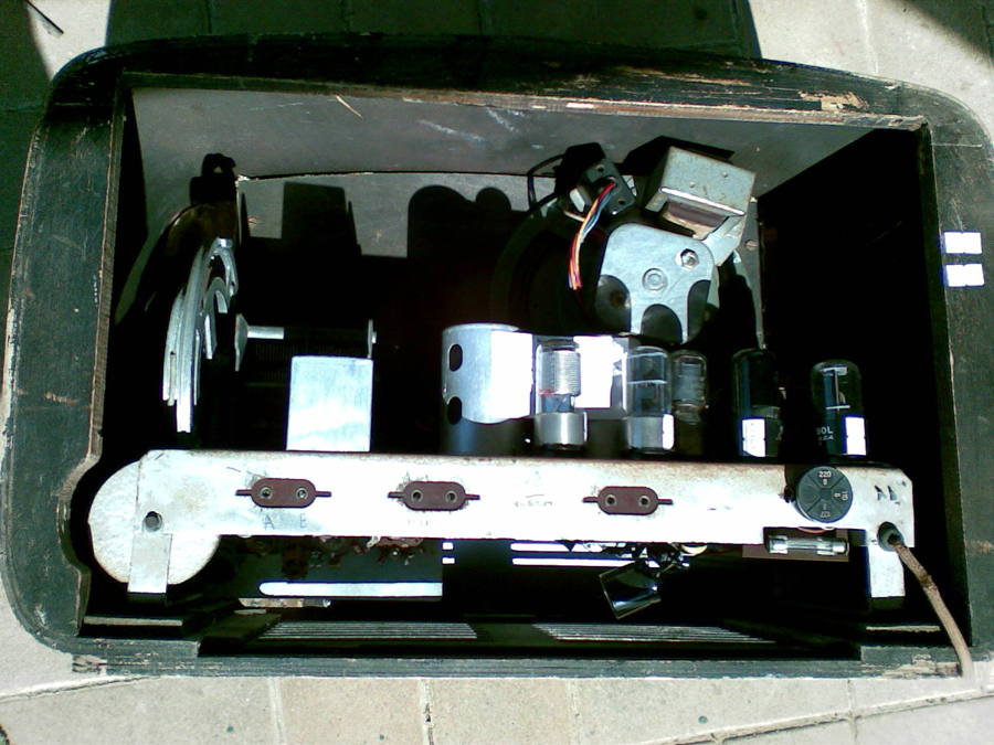
A few years back I bought a radio from the Soviet era. It has the Russian markings and so on, but the valves are standard octal types. It also has a tuning indicator that doesn't work. |
|
|
Return to top of page · Post #: 2 · Written at 1:31:29 PM on 4 April 2018.
|
|
|
|
Location: Belrose, NSW
Member since 31 December 2015 Member #: 1844 Postcount: 2628 |
|
Anything's possible, there was apparently pressure to get those things out the door to meet quotas despite missing parts. |
|
|
Return to top of page · Post #: 3 · Written at 1:53:12 PM on 4 April 2018.
|
|
|
|
Location: Latham, ACT
Member since 21 February 2015 Member #: 1705 Postcount: 2216 |
|
Send photos buddy |
|
|
Return to top of page · Post #: 4 · Written at 11:46:20 PM on 4 April 2018.
|
|
|
|
Location: Wangaratta, VIC
Member since 21 February 2009 Member #: 438 Postcount: 5595 |
|
The resistors on a tuning indicator have an attrition rate, like wax paper caps, never to be left unchecked. We also have the issue of no AGC voltage. |
|
|
Return to top of page · Post #: 5 · Written at 8:47:32 AM on 6 April 2018.
|
|
|
|
Location: Beechmont, QLD
Member since 10 April 2009 Member #: 465 Postcount: 109 |
|
If the reception is weak, there is likely a problem or problems in the front end. These can be anything; misalignment, resistors gone high, faulty valves, I.F. transformers lost their "Q", open windings, leaky capacitors, capacitors with high ESR, especially mica types, etc. Dozens more possible causes. It is puzzling that the triode part of the 6SQ7 is not connected. Is there another audio driver used? Is the 6SQ7 the correct valve for that socket? |
|
|
Return to top of page · Post #: 6 · Written at 7:46:38 PM on 6 April 2018.
|
|
|
|
Location: Hill Top, NSW
Member since 18 September 2015 Member #: 1801 Postcount: 2193 |
|
No problem with reception, it's just the volume is a bit lower than i'd expect with the number of valves it has. |
|
|
Return to top of page · Post #: 7 · Written at 8:25:51 PM on 6 April 2018.
|
|
|
|
Location: Wangaratta, VIC
Member since 21 February 2009 Member #: 438 Postcount: 5595 |
|
The greatest cause of "deaf sets" relates to alignment: What is often overlooked for on, is the recommendation by manufacturers, to re-align if RF parts have been changed. |
|
|
Return to top of page · Post #: 8 · Written at 11:02:18 PM on 9 April 2018.
|
|
|
|
Location: Hill Top, NSW
Member since 18 September 2015 Member #: 1801 Postcount: 2193 |
|
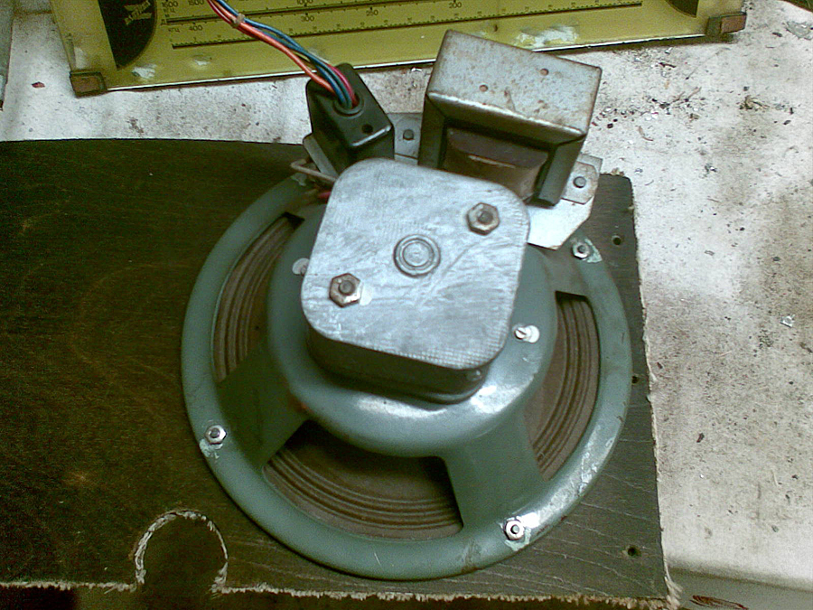
Photos sent to Brad.     |
|
|
Return to top of page · Post #: 9 · Written at 11:08:52 PM on 9 April 2018.
|
|
|
|
Location: Belrose, NSW
Member since 31 December 2015 Member #: 1844 Postcount: 2628 |
|
Sounds like it's low in gain which, with that valve lineup, it shouldn't be. First, have a look at plate and screen voltages - you might have a screen dropper resistor that's gone high or a leaky bypass cap or 2 or 3.... |
|
|
Return to top of page · Post #: 10 · Written at 1:50:21 AM on 10 April 2018.
|
|
|
|
Location: Wangaratta, VIC
Member since 21 February 2009 Member #: 438 Postcount: 5595 |
|
6U5 needs around -22V Grid bias |
|
|
Return to top of page · Post #: 11 · Written at 10:15:22 PM on 10 April 2018.
|
|
|
|
Administrator
Location: Naremburn, NSW
Member since 15 November 2005 Member #: 1 Postcount: 7548 |
|
Photos uploaded to Post 8. ‾‾‾‾‾‾‾‾‾‾‾‾‾‾‾‾‾‾‾‾‾‾‾‾‾‾‾‾‾‾‾‾‾‾‾‾‾‾‾‾‾‾‾‾‾‾‾‾‾‾‾‾‾‾‾‾‾‾‾‾‾‾‾‾‾‾‾‾ A valve a day keeps the transistor away... |
|
|
Return to top of page · Post #: 12 · Written at 7:32:27 AM on 11 April 2018.
|
|
|
|
Location: Hill Top, NSW
Member since 18 September 2015 Member #: 1801 Postcount: 2193 |
|
Thanks Brad. |
|
|
Return to top of page · Post #: 13 · Written at 10:41:06 AM on 11 April 2018.
|
|
|
|
Location: Wangaratta, VIC
Member since 21 February 2009 Member #: 438 Postcount: 5595 |
|
There are odd things about it and I am wondering if its an under licence job? The tuning gang is more like the Stromberg Carlson types and Philips were one that used big cable drums like that. |
|
|
Return to top of page · Post #: 14 · Written at 11:58:33 AM on 13 April 2018.
|
|
|
|
Location: Mount Lawley, WA
Member since 12 September 2017 Member #: 2167 Postcount: 49 |
|
I asked a friend in Ukraine to identify the radio. |
|
|
Return to top of page · Post #: 15 · Written at 8:38:18 PM on 14 April 2018.
|
|
|
|
Location: Hill Top, NSW
Member since 18 September 2015 Member #: 1801 Postcount: 2193 |
|
Nhanwell, thanks very much! |
|
|
You need to be a member to post comments on this forum.
|
|

Sign In

Vintage Radio and Television is proudly brought to you by an era where things were built with pride and made to last.
DISCLAIMER: Valve radios and televisions contain voltages that can deliver lethal shocks. You should not attempt to work on a valve radio or other electrical appliances unless you know exactly what you are doing and have gained some experience with electronics and working around high voltages. The owner, administrators and staff of Vintage Radio & Television will accept no liability for any damage, injury or loss of life that comes as a result of your use or mis-use of information on this website. Please read our Safety Warning before using this website.
WARNING: Under no circumstances should you ever apply power to a vintage radio, television or other electrical appliance you have acquired without first having it checked and serviced by an experienced person. Also, at no time should any appliance be connected to an electricity supply if the power cord is damaged. If in doubt, do not apply power.
Shintara - Keepin' It Real · VileSilencer - Maintain The Rage

