
Tech Talk
Forum home - Go back to Tech talk
|
AWA B92 adjustments
|
|
|
Return to top of page · Post #: 1 · Written at 11:22:59 AM on 22 February 2018.
|
|

|
Location: Daylesford, VIC
Member since 13 January 2011 Member #: 809 Postcount: 326 |
|
The AWA B92 chassis I'm repairing is now complete. The first question is, what's the ideal quiescent current for the 2N2955 output transistors? The left channel's conducting about 7mA (it varies a bit, which is a worry), and the right channel's not conducting at all. |
|
|
Return to top of page · Post #: 2 · Written at 12:42:49 PM on 22 February 2018.
|
|

|
Location: Wangaratta, VIC
Member since 21 February 2009 Member #: 438 Postcount: 5715 |
|
I would expect the base to draw 7mA The transistor is good for 15A PNP. Check wiring. |
|
|
Return to top of page · Post #: 3 · Written at 1:57:55 PM on 22 February 2018.
|
|
|
|
Location: Belrose, NSW
Member since 31 December 2015 Member #: 1844 Postcount: 2710 |
|
But the quiescent current should be as low as possible 7mA sounds about right. |
|
|
Return to top of page · Post #: 4 · Written at 6:17:22 PM on 22 February 2018.
|
|
|
|
Location: Daylesford, VIC
Member since 13 January 2011 Member #: 809 Postcount: 326 |
|
OK, the right channel's working now, it was a bad transistor socket. But both channels tend to run out of control after a few minutes, with the current going up to 200mA. I used the three silicon diodes for bias of the drivers as you suggested Ian, but now I've changed it back to two diodes plus a 1K trimmer so I can keep a possible runaway under control. At the moment the problem is the BC547 NPN drivers overheating badly. They get too hot to touch. Even if I changed the NPN to the original AS147 or BC147 they'd still be hot. The PNP drivers are staying cool, though. Just to see, I changed one output pair from silicon 2N2955 to germanium OC26, and the corresponding NPN driver stopped overheating. So perhaps I should go with germanium for output as the amp had originally? 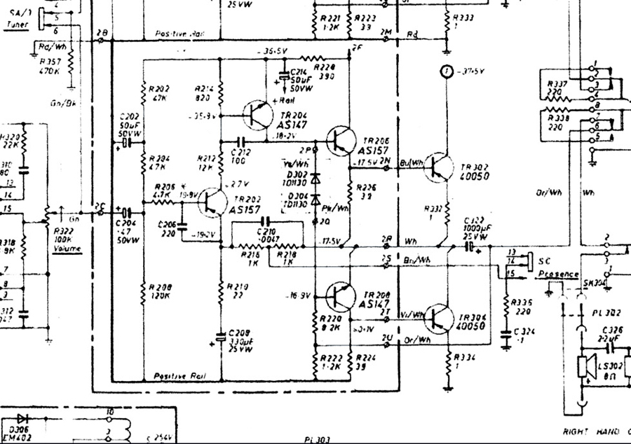 |
|
|
Return to top of page · Post #: 5 · Written at 8:28:30 PM on 22 February 2018.
|
|
|
|
Location: Belrose, NSW
Member since 31 December 2015 Member #: 1844 Postcount: 2710 |
|
Not sure why without having a good look at the circuit but if the OC26s work and you have them, I'd go with that. |
|
|
Return to top of page · Post #: 6 · Written at 8:56:52 PM on 22 February 2018.
|
|
|
|
Location: Belrose, NSW
Member since 31 December 2015 Member #: 1844 Postcount: 2710 |
|
Another thought... |
|
|
Return to top of page · Post #: 7 · Written at 9:18:32 PM on 22 February 2018.
|
|
|
|
Location: Daylesford, VIC
Member since 13 January 2011 Member #: 809 Postcount: 326 |
|
No, the screw contact is good. Actually it was the NPN drivers overheating, I misread the circuit and made a mistake in my post. Corrected now. I think it's the extra bias requirement for silicon transistors that's overheating the NPNs. If I wind the trimpot back they cool down, but that turns off the output transistors. |
|
|
Return to top of page · Post #: 8 · Written at 9:35:52 PM on 22 February 2018.
|
|

|
Location: Melbourne, VIC
Member since 20 September 2011 Member #: 1009 Postcount: 1263 |
|
Would matched pairs of NOS AD149's be any good? |
|
|
Return to top of page · Post #: 9 · Written at 11:31:53 PM on 22 February 2018.
|
|
|
|
Location: Daylesford, VIC
Member since 13 January 2011 Member #: 809 Postcount: 326 |
|
Perfect! They're very like the OC26's, so I'd only need one pair. |
|
|
Return to top of page · Post #: 10 · Written at 9:16:25 AM on 23 February 2018.
|
|
|
|
Location: Belrose, NSW
Member since 31 December 2015 Member #: 1844 Postcount: 2710 |
|
You might still have a problem if the beta is low, but yes, AD149s should work. |
|
|
Return to top of page · Post #: 11 · Written at 5:38:32 PM on 23 February 2018.
|
|

|
Location: Hobart, TAS
Member since 31 July 2016 Member #: 1959 Postcount: 605 |
|
I’ve got a couple of 2N301’s you can have, same gain. |
|
|
Return to top of page · Post #: 12 · Written at 5:57:38 PM on 23 February 2018.
|
|
|
|
Location: Belrose, NSW
Member since 31 December 2015 Member #: 1844 Postcount: 2710 |
|
They should work, lower Ft tho... |
|
|
Return to top of page · Post #: 13 · Written at 7:04:04 PM on 23 February 2018.
|
|

|
Administrator
Location: Naremburn, NSW
Member since 15 November 2005 Member #: 1 Postcount: 7624 |
|
Circuit uploaded to Post 4. ‾‾‾‾‾‾‾‾‾‾‾‾‾‾‾‾‾‾‾‾‾‾‾‾‾‾‾‾‾‾‾‾‾‾‾‾‾‾‾‾‾‾‾‾‾‾‾‾‾‾‾‾‾‾‾‾‾‾‾‾‾‾‾‾‾‾‾‾ A valve a day keeps the transistor away... |
|
|
Return to top of page · Post #: 14 · Written at 7:40:41 PM on 23 February 2018.
|
|
|
|
Location: Belrose, NSW
Member since 31 December 2015 Member #: 1844 Postcount: 2710 |
|
Put the 2N2955s back in and fit 39 ohm or 47 ohm in series with the base of TR304, i.e. the lower output transistor. |
|
|
Return to top of page · Post #: 15 · Written at 12:11:54 AM on 4 March 2018.
|
|
|
|
Location: Daylesford, VIC
Member since 13 January 2011 Member #: 809 Postcount: 326 |
|
All working properly now, with OC26's on one channel and 2N301's on the other. The last step was replacing some badly drifted carbon composition resistors in the tone circuit to get both channels approximately equal in volume and quality. Thanks for the help, everyone. |
|
|
You need to be a member to post comments on this forum.
|
|
Sign In
Vintage Radio and Television is proudly brought to you by an era where things were built with pride and made to last.
DISCLAIMER: Valve radios and televisions contain voltages that can deliver lethal shocks. You should not attempt to work on a valve radio or other electrical appliances unless you know exactly what you are doing and have gained some experience with electronics and working around high voltages. The owner, administrators and staff of Vintage Radio & Television will accept no liability for any damage, injury or loss of life that comes as a result of your use or mis-use of information on this website. Please read our Safety Warning before using this website.
WARNING: Under no circumstances should you ever apply power to a vintage radio, television or other electrical appliance you have acquired without first having it checked and serviced by an experienced person. Also, at no time should any appliance be connected to an electricity supply if the power cord is damaged. If in doubt, do not apply power.
Shintara - Keepin' It Real · VileSilencer - Maintain The Rage