Welcome to Australia's only Vintage Radio and Television discussion forums. You are not logged in. Please log in below, apply for an account or retrieve your password.
Australian Vintage Radio Forums
  Home  ·  About Us  ·  Discussion Forums  ·  Glossary  ·  Outside Links  ·  Policies  ·  Services Directory  ·  Safety Warnings  ·  Tutorials

Tech Talk

Forum home - Go back to Tech talk

 Radio receiver Model 69 by 'radio manufacturing engineers'
« Back · 1 · 2 · Next »
 Return to top of page · Post #: 1 · Written at 4:57:46 PM on 21 January 2018.
Fred Lever's Gravatar
 Location: Toongabbie, NSW
 Member since 19 November 2015
 Member #: 1828
 Postcount: 1250

Check this set out guys.
I was given this from an old gent as too good to scrap and needs to go to a good home.
It has 11 valves and more IF cans you can poke a stick at.
The tuning has multiple ranges from KC to many Mcs by a switch and a clutch of coils.
Looks to me like a professional communication receiver with a mixture of Philips octal valves and USA metal octal and old school 6 pin.
Valve line up is P, P, 6L7, 6K7, 6J7, 6H6, P 6B7, 42, 80, 6D6. "P" is a red coat Philips octal but the red stuff has flaked off those 3 valves hence no type number.
It weighs a ton, a good lift for one with a sand cast chassis and steel box with a lift up top lid so you can reach in and burn yourself on the valves.
There is a nameplate on the back but oddly not a trace of writing around the knobs to tell you what does what.
Maybe a "built to spec" job to order?
I'll send a bunch of Jpgs to Brad.
Anybody know what it is, who, how ect.
Fred.

Unknown Radio
Unknown Radio
Unknown Radio
Unknown Radio
Unknown Radio
Unknown Radio


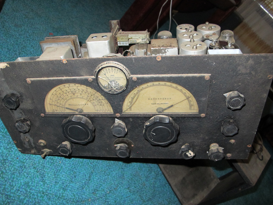
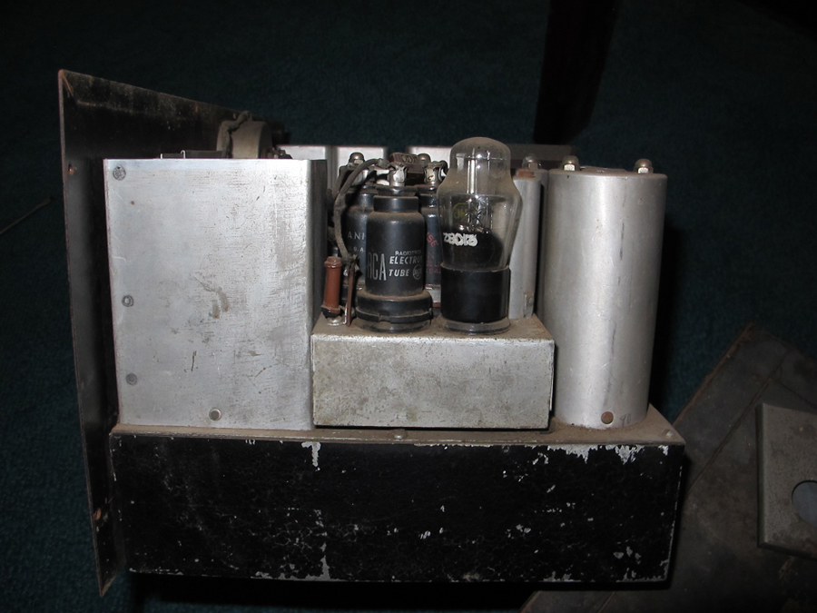
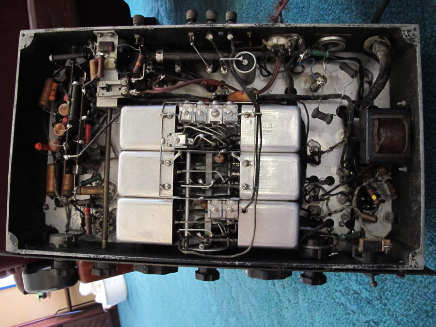
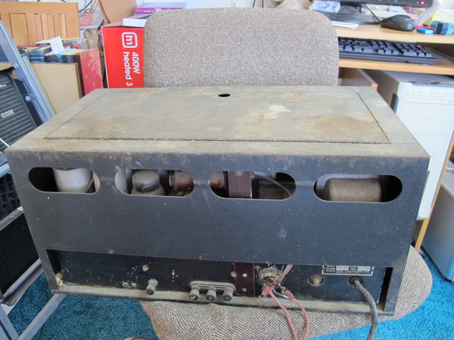
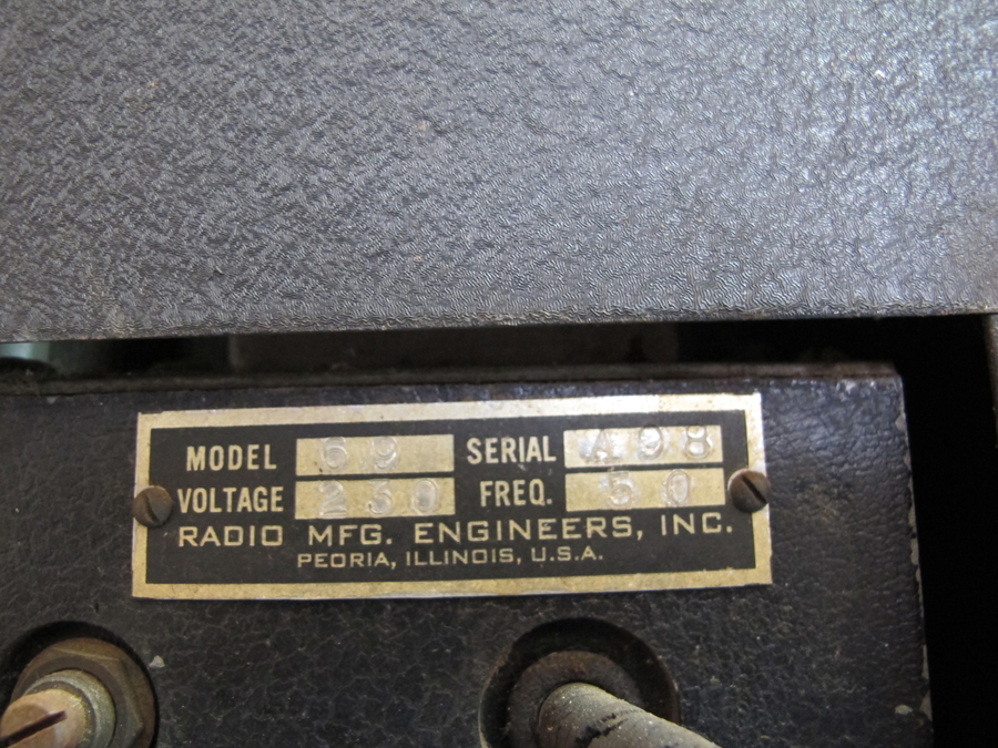
 Return to top of page · Post #: 2 · Written at 9:15:41 PM on 21 January 2018.
BringBackTheValve's Gravatar
 Location: Linton, VIC
 Member since 30 December 2016
 Member #: 2028
 Postcount: 467

Manufactured in USA, 50Hz Mains----???

Made for the Commonwealth?


 Return to top of page · Post #: 3 · Written at 9:23:51 PM on 21 January 2018.
Bushman's Gravatar
 Location: Kempsey, NSW
 Member since 6 December 2016
 Member #: 2019
 Postcount: 37

Hi Fred,
Type in your search engine the radio manufacturer's name and radiomuseum and you will find a list of models made. For your radio it is a RME69 Model and the site includes photo and even better a circuit to assist in determining the functions of the control knob. Hope this helps.
Bushman


 Return to top of page · Post #: 4 · Written at 10:21:16 PM on 21 January 2018.
Marcc's avatar
 Location: Wangaratta, VIC
 Member since 21 February 2009
 Member #: 438
 Postcount: 5254

Possibly NATO that's the std European voltage.


 Return to top of page · Post #: 5 · Written at 11:05:03 PM on 21 January 2018.
GTC's avatar
 GTC
 Location: Sydney, NSW
 Member since 28 January 2011
 Member #: 823
 Postcount: 6687

Here you go Fred, I'll save you the trouble:

https://www.radiomuseum.org/r/radio26_69a.html


 Return to top of page · Post #: 6 · Written at 8:27:40 AM on 22 January 2018.
Fred Lever's Gravatar
 Location: Toongabbie, NSW
 Member since 19 November 2015
 Member #: 1828
 Postcount: 1250

Hi Guys, thanks so much, that info will make it easy to get this baby going again.
I now realise its a low number production commercial item and mine was made where they were moving from 6 pin to octal types?
The octal sockets are all ceramic, I wonder if maybe its been upgraded as there is a real mix of component types and year styles. Some of the caps and resistors look like aussie types.
There are a few obvious mods, the relay perching on top of the stick of Bakelite is obvious, but I would imagine any work on it would have been to keep it going for commercial use and not "valve jockey" suburban level.
I'll take it very slow on this one and just refurb it to going condition by component replacement and clean it up but leave the patina as is.
Fred.


 Return to top of page · Post #: 7 · Written at 11:55:47 AM on 22 January 2018.
Tinkera123's Gravatar
 Location: Melbourne, VIC
 Member since 5 October 2009
 Member #: 555
 Postcount: 465

Now that's a nice challenge .... Smile

Can we expect to be kept updated with your usual write-ups Fred????


‾‾‾‾‾‾‾‾‾‾‾‾‾‾‾‾‾‾‾‾‾‾‾‾‾‾‾‾‾‾‾‾‾‾‾‾‾‾‾‾‾‾‾‾‾‾‾‾‾‾‾‾‾‾‾‾‾‾‾‾‾‾‾‾‾‾‾‾
Cheers, Ian

 
 Return to top of page · Post #: 8 · Written at 7:01:27 PM on 22 January 2018.
Fred Lever's Gravatar
 Location: Toongabbie, NSW
 Member since 19 November 2015
 Member #: 1828
 Postcount: 1250

Hi Ian, yep i'll start a folder in my system and write up whatever I do.
This will be interesting when I get to it as having had a look at the original circuit this unit has been hacked well and truly about the front end.
The 2nd IF valve has been removed completely and in its place has been substituted a sub chassis that you can see in the photos.
That has a 6L7, 6K7, 6J7, 6H6 on it so may be another frequency changer stage or whole something else.
I think its had a turbo charger bolted on and nitro bottles added! (if it was a car).
The power supply 80, the 42 and 6A7 forming the detector and audio still look original as does the oscillator and BFO sections.
The RF and mixer valves are part of the hack being 2 of the red Philips octal valves, probably higher gain types than the originals and that is why the parts around that section are aussie wax caps and resistors like IRC and Ducon style parts.
I've got too much on in the workshop to do any more so its going to hang as a mystery until I can get it up on a bench and make it safe to power.
I'm still 1/2 way through the Bass guitar and 1/4 way through the Bass amplifier and someone has to make the cabinet for the 3" TV chassis from last year!
So much to do and so little time to do it.
Fred.


 Return to top of page · Post #: 9 · Written at 1:54:26 AM on 24 January 2018.
Marcc's avatar
 Location: Wangaratta, VIC
 Member since 21 February 2009
 Member #: 438
 Postcount: 5254

I have a specific sub directory "Radio Sets". That runs in brands. Sets like the HMV I just repaired will have any photos circuit & notes on mods stored there in another folder for its model. Any stray info that turns up like factory info on a particular set, also goes in that folder, unless its non specific.

Very handy reference material.

Marc


 Return to top of page · Post #: 10 · Written at 8:24:34 AM on 24 January 2018.
Fred Lever's Gravatar
 Location: Toongabbie, NSW
 Member since 19 November 2015
 Member #: 1828
 Postcount: 1250

Having done a bit of reading about RME and a closer look doing a survey on the bench I now recognise some things:
1/ my set has the optional noise limiter that's the 4 valve chassis plugged into the two IF valve sockets.
2/ RME simply did not mark their front panels for control function. I wont promote the fantasy storys here about why, I spend enough time debunking fairy storys about Australian coins to start with radios.
3/ my set has the pencilled initials of the guys that made it, one next to the RF valve "BW" one near the rectifier "CM" ? (I've forgotten the guys name I did read it in the RME history but i'm having a senior moment here) and on the coil set a "W7" plus a tiny initial that looks like an '8' on its side..
3/ the octal valve sockets used for the RF, mixer and BFO look original with the same chassis fixings as the 6 pin sockets and the soldering looks original, apart from replaced parts .
4/ the rats have been into the set over the years but the core of it, the coil set is untouched and solid.

The 240 wiring is a horror, the 240 mains wires wander around the chassis and wind up on the back of a pot in the oscillator shield box diagonally opposite the cord entry!! No way is that going to stay like that, i'll fit an on/off switch at the back of the set and get rid of the crumbling wires. The on/off switch at the front of the panel is haywired to the BFO HT as a BFO on/off, that cant be original as the circuit shows a multi pole switch operated as a push pull on one of the other knobs, just a mystery to sort out.
Have not powered anything up yet still surveying and taking photos.
Fun!


 Return to top of page · Post #: 11 · Written at 9:58:31 AM on 24 January 2018.
Marcc's avatar
 Location: Wangaratta, VIC
 Member since 21 February 2009
 Member #: 438
 Postcount: 5254

I really have no issues with not powering it. I will not power any set without inspection, rare exceptions are those that come in barely working, even then it will not escape inspection. Some are just too dangerous to power and others will let the smoke out.

They deteriorate sitting & were often abandoned when they broke down. So are likely faulty & powering to see if it works is the first serious and possibly dangerous mistake. Had one where that happened last year... parts destroyed... pan powder coated.

I have commented on one that came in, where I was amazed that the owner was not killed unplugging it, or it had not started a fire: Rubber figure 8 mains lead with bare patches & well past its use by date. That one left with a three wire cable.

Marc


 Return to top of page · Post #: 12 · Written at 12:18:40 PM on 24 January 2018.
Fred Lever's Gravatar
 Location: Toongabbie, NSW
 Member since 19 November 2015
 Member #: 1828
 Postcount: 1250

Exactly Marc, I did not mention it but have taken a photo, the 100 year old rubber power cord looked ok at a glance.
However inside the power plug the rubber had rotted off the A,N wires just where they go in the plug.
Thus the bare cores were WRAPPED AROUND each other!!
I would have found that on my short circuit and earth continuity test anyway if I had not cut the cord off.

If I had been a "gung ho" type and just plugged it in , it would have been "flash bang wallop" like that recent HR meet and go and reset all the breakers!

Fred.


 Return to top of page · Post #: 13 · Written at 4:03:08 PM on 24 January 2018.
Ian Robertson's Gravatar
 Location: Belrose, NSW
 Member since 31 December 2015
 Member #: 1844
 Postcount: 2370

Hi Fred

Do you have the full circuit of this beast?
The noise blanker option rang a bell from a long time ago. It was called a Lamb Noise Silencer I seem to recall. Worked on the signal before it got to the IFs where spikes could be gated out before they got broadened by ringing in the IFs.


 Return to top of page · Post #: 14 · Written at 5:41:28 PM on 24 January 2018.
Marcc's avatar
 Location: Wangaratta, VIC
 Member since 21 February 2009
 Member #: 438
 Postcount: 5254

I will often go one step further & attack the whole transformer with the insulation tester, otherwise the primary side cops it anyway (Tag & Test)


 Return to top of page · Post #: 15 · Written at 7:00:40 PM on 24 January 2018.
Fred Lever's Gravatar
 Location: Toongabbie, NSW
 Member since 19 November 2015
 Member #: 1828
 Postcount: 1250

Hi Ian, yes thanks, I downloaded the handbook with all circuit variants, control diagrams, alinement details from the "boat anchor" web site.
A great source of info for old equipment.
Cheers, Fred.


« Back · 1 · 2 · Next »
 You need to be a member to post comments on this forum.

Sign In

Username:
Password:
 Keep me logged in.
Do not tick box on a computer with public access.