Tech Talk
Forum home - Go back to Tech talk
|
Another way to ruin modern equipment
|
|
|
« Back ·
1 ·
Next »
|
|
|
Return to top of page · Post #: 1 · Written at 8:59:39 AM on 18 January 2018.
|
|
|
|
Location: Oradell, US
Member since 2 April 2010 Member #: 643 Postcount: 835 |
|
I was trying to modify a Linksys WRT54G OpenWRT router to install a USB port. See: |
|
|
Return to top of page · Post #: 2 · Written at 10:43:21 AM on 18 January 2018.
|
|
|
|
Location: Belrose, NSW
Member since 31 December 2015 Member #: 1844 Postcount: 2677 |
|
You need a hot air SMD rework tool with a fine nozzle. tweezers and a magnifier lamp for that sort of work |
|
|
Return to top of page · Post #: 3 · Written at 10:41:43 PM on 18 January 2018.
|
|
|
|
Location: Brunswick, VIC
Member since 3 May 2017 Member #: 2100 Postcount: 43 |
|
I know your pain. I work on SMD PCBs all the time and I need the magnifier just to see the components. My preferred method of removing resistors without the hot air rework station is just to heat both ends quickly in succession and flick the resistor off with the soldering iron tip. After a few thousand goes you get it down to a fine art. |
|
|
Return to top of page · Post #: 4 · Written at 11:14:38 PM on 18 January 2018.
|
|
|
|
Administrator
Location: Naremburn, NSW
Member since 15 November 2005 Member #: 1 Postcount: 7590 |
|
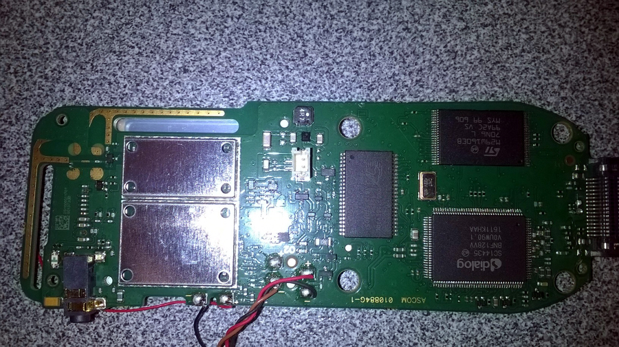
The closest I come to working on stuff like that is when I need to repair Ericsson/Aastra/Mitel DECT phones at work, which get dropped and otherwise abused by the lucky people that don't have to pay for their repair or replacement. The SMDs on these phones are about half the size of those pictured on the modem's motherboard above so I don't even try with those. The bits that would normally be repairable/replaceable are the screens and microphones but even these are too hard to handle these days due to the stupid lead-free solder used in the manufacture (it sets too quickly to successfully unsolder a screen's ribbon cable) and the delicate nature of the microphones, as they simply cannot handle the heat from my iron).  ‾‾‾‾‾‾‾‾‾‾‾‾‾‾‾‾‾‾‾‾‾‾‾‾‾‾‾‾‾‾‾‾‾‾‾‾‾‾‾‾‾‾‾‾‾‾‾‾‾‾‾‾‾‾‾‾‾‾‾‾‾‾‾‾‾‾‾‾ A valve a day keeps the transistor away... |
|
|
Return to top of page · Post #: 5 · Written at 11:34:16 PM on 18 January 2018.
|
|
|
|
Location: Sydney, NSW
Member since 28 January 2011 Member #: 823 Postcount: 6911 |
|
A friend who works on SMD stuff frequently has invested in an industrial quality electronic microscope after growing tired of the el cheapo $60 version he'd been struggling with. I thought he was crazy to pay $4K for the new one but it makes a huge difference and has paid for itself many times over. |
|
|
Return to top of page · Post #: 6 · Written at 8:31:05 AM on 19 January 2018.
|
|
|
|
Location: Belrose, NSW
Member since 31 December 2015 Member #: 1844 Postcount: 2677 |
|
Yes I do a bit of SMD rework/prototyping. Down to 0603 chip parts and 0.4mm pitch QFPs. |
|
|
Return to top of page · Post #: 7 · Written at 10:16:23 AM on 19 January 2018.
|
|
|
|
Location: Oradell, US
Member since 2 April 2010 Member #: 643 Postcount: 835 |
|
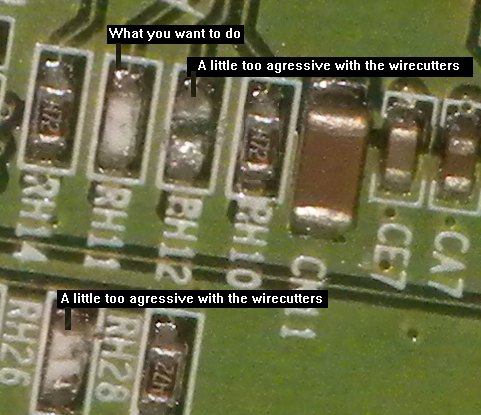
I did some practice with the ruined router board, and found that all I really need do is to chip the resistor enough that I can see the white ceramic substrate, as a gap that crosses the resistor body. So that the resistive material is broken between the solder ends. It won't look pretty, but this should be less trauma to the circuit board. I'll solder the new connection or part atop that. As I said, not pretty... But should be less risky give the crudeness of my tools. (You heard the one about the workman blaming his tools...) |
|
|
Return to top of page · Post #: 8 · Written at 8:47:23 PM on 21 January 2018.
|
|
|
|
Administrator
Location: Naremburn, NSW
Member since 15 November 2005 Member #: 1 Postcount: 7590 |
|
Photo uploaded to Post 4. ‾‾‾‾‾‾‾‾‾‾‾‾‾‾‾‾‾‾‾‾‾‾‾‾‾‾‾‾‾‾‾‾‾‾‾‾‾‾‾‾‾‾‾‾‾‾‾‾‾‾‾‾‾‾‾‾‾‾‾‾‾‾‾‾‾‾‾‾ A valve a day keeps the transistor away... |
|
|
Return to top of page · Post #: 9 · Written at 4:20:00 PM on 4 March 2018.
|
|
|
|
Location: Somewhere, USA
Member since 22 October 2013 Member #: 1437 Postcount: 896 |
|
Before anything else, you need a roll of wrap wire. You’re punishing yourself as soon as you started on that. |
|
|
« Back ·
1 ·
Next »
|
|
|
You need to be a member to post comments on this forum.
|
|

Sign In

Vintage Radio and Television is proudly brought to you by an era where things were built with pride and made to last.
DISCLAIMER: Valve radios and televisions contain voltages that can deliver lethal shocks. You should not attempt to work on a valve radio or other electrical appliances unless you know exactly what you are doing and have gained some experience with electronics and working around high voltages. The owner, administrators and staff of Vintage Radio & Television will accept no liability for any damage, injury or loss of life that comes as a result of your use or mis-use of information on this website. Please read our Safety Warning before using this website.
WARNING: Under no circumstances should you ever apply power to a vintage radio, television or other electrical appliance you have acquired without first having it checked and serviced by an experienced person. Also, at no time should any appliance be connected to an electricity supply if the power cord is damaged. If in doubt, do not apply power.
Shintara - Keepin' It Real · VileSilencer - Maintain The Rage


