
Tech Talk
Forum home - Go back to Tech talk
|
Circuit Analysis: 1950's Philco Hi-Fi
|
|
|
Return to top of page · Post #: 1 · Written at 1:18:56 AM on 31 December 2017.
|
|
|
Location: Silver City WI, US
Member since 10 May 2013 Member #: 1340 Postcount: 977 |
|
This topic extends the discussion on unusual Kriesler amplifier design on another thread. Of particular interest is Philco's take on "See-Saw-paraphase" push-pull drivers - a design that first appeared just after WWII. 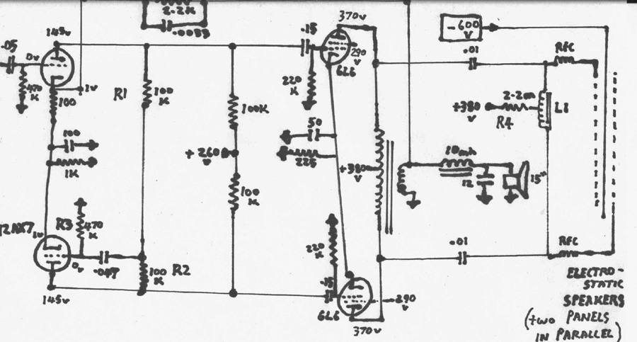 |
|
|
Return to top of page · Post #: 2 · Written at 3:06:25 PM on 31 December 2017.
|
|
|
|
Location: Silver City WI, US
Member since 10 May 2013 Member #: 1340 Postcount: 977 |
|
So first tech question I have is why do they have RF chokes in series on drives to the stator plates of electrostatic panels? |
|
|
Return to top of page · Post #: 3 · Written at 5:46:17 PM on 31 December 2017.
|
|
|
|
Location: Belrose, NSW
Member since 31 December 2015 Member #: 1844 Postcount: 2710 |
|
I suggest you download and install LTSpice. It's a free download. Spend a few hours learning how to use it. |
|
|
Return to top of page · Post #: 4 · Written at 8:31:04 PM on 31 December 2017.
|
|
|
|
Location: Linton, VIC
Member since 30 December 2016 Member #: 2028 Postcount: 472 |
|
Re: RF Chokes, |
|
|
Return to top of page · Post #: 5 · Written at 8:48:32 PM on 31 December 2017.
|
|
|
|
Location: Linton, VIC
Member since 30 December 2016 Member #: 2028 Postcount: 472 |
|
Hi New Vista, |
|
|
Return to top of page · Post #: 6 · Written at 8:01:45 AM on 1 January 2018.
|
|
|
|
Location: Linton, VIC
Member since 30 December 2016 Member #: 2028 Postcount: 472 |
|
Additional comment re: RCF and proposed bypass cap--- |
|
|
Return to top of page · Post #: 7 · Written at 8:28:31 AM on 1 January 2018.
|
|

|
Location: Wangaratta, VIC
Member since 21 February 2009 Member #: 438 Postcount: 5715 |
|
I do also wonder if there is a risk, with RF getting into those speakers? Whilst a bit of RF may help a valve run at a steadier current, many audio valves have little problem with amplifying it. |
|
|
Return to top of page · Post #: 8 · Written at 9:36:41 AM on 1 January 2018.
|
|
|
|
Location: Linton, VIC
Member since 30 December 2016 Member #: 2028 Postcount: 472 |
|
Good point. |
|
|
Return to top of page · Post #: 9 · Written at 10:23:03 AM on 1 January 2018.
|
|
|
|
Location: Belrose, NSW
Member since 31 December 2015 Member #: 1844 Postcount: 2710 |
|
Reason for the RFCs is to restrict capacitive loading on the amp due to the fact that the capacitive reactance of electrostatic speakers drops with increasing frequency. |
|
|
Return to top of page · Post #: 10 · Written at 11:46:49 AM on 1 January 2018.
|
|

|
Location: Hobart, TAS
Member since 31 July 2016 Member #: 1959 Postcount: 605 |
|
Ian, A small guitar amp would make a great winter's project. |
|
|
Return to top of page · Post #: 11 · Written at 3:17:45 PM on 1 January 2018.
|
|
|
|
Location: Silver City WI, US
Member since 10 May 2013 Member #: 1340 Postcount: 977 |
|
I will tell our hobby group about LTSpice (have not checked it out yet)
Interestingly, we had trouble with unstable ultrasonics on this 6L6 amp which only disappeared when .0033 cap was removed from feedback line! Though to be fair, the 100k/half-watt resistors need changing as they measure out of spec (most went low to around 84k)(so case not closed on this yet.) Philco's later Anode Follower 6BQ5 amp also has a "large" .0033 cap for feedback compensation while their Williamson version, as you'll note from link, only needs a mere 100pf. |
|
|
Return to top of page · Post #: 12 · Written at 8:53:37 PM on 2 January 2018.
|
|
|
|
Location: Linton, VIC
Member since 30 December 2016 Member #: 2028 Postcount: 472 |
|
NewVista, |
|
|
Return to top of page · Post #: 13 · Written at 9:05:40 PM on 2 January 2018.
|
|
|
|
Location: Linton, VIC
Member since 30 December 2016 Member #: 2028 Postcount: 472 |
|
If they read 84K, I would not replace them, they are probably OK. |
|
|
Return to top of page · Post #: 14 · Written at 9:09:19 PM on 2 January 2018.
|
|
|
|
Location: Linton, VIC
Member since 30 December 2016 Member #: 2028 Postcount: 472 |
|
Another thought. |
|
|
Return to top of page · Post #: 15 · Written at 12:20:41 AM on 3 January 2018.
|
|
|
|
Location: Wangaratta, VIC
Member since 21 February 2009 Member #: 438 Postcount: 5715 |
|
Many resistors read low, if measured "in circuit" One should be aware if that, should it occur. |
|
|
You need to be a member to post comments on this forum.
|
|
Sign In
Vintage Radio and Television is proudly brought to you by an era where things were built with pride and made to last.
DISCLAIMER: Valve radios and televisions contain voltages that can deliver lethal shocks. You should not attempt to work on a valve radio or other electrical appliances unless you know exactly what you are doing and have gained some experience with electronics and working around high voltages. The owner, administrators and staff of Vintage Radio & Television will accept no liability for any damage, injury or loss of life that comes as a result of your use or mis-use of information on this website. Please read our Safety Warning before using this website.
WARNING: Under no circumstances should you ever apply power to a vintage radio, television or other electrical appliance you have acquired without first having it checked and serviced by an experienced person. Also, at no time should any appliance be connected to an electricity supply if the power cord is damaged. If in doubt, do not apply power.
Shintara - Keepin' It Real · VileSilencer - Maintain The Rage