
Tech Talk
Forum home - Go back to Tech talk
|
1931 AWA Radiola 45E Model C79
|
|
|
Return to top of page · Post #: 1 · Written at 9:09:37 AM on 23 October 2017.
|
|

|
Location: Adelaide, SA
Member since 27 February 2010 Member #: 630 Postcount: 398 |
|
Hi All 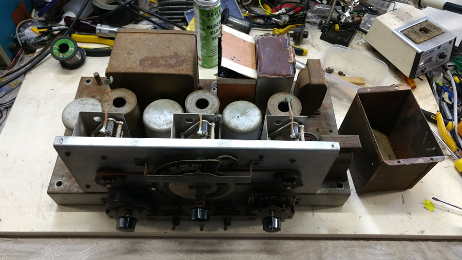 Any help is appreciated. ‾‾‾‾‾‾‾‾‾‾‾‾‾‾‾‾‾‾‾‾‾‾‾‾‾‾‾‾‾‾‾‾‾‾‾‾‾‾‾‾‾‾‾‾‾‾‾‾‾‾‾‾‾‾‾‾‾‾‾‾‾‾‾‾‾‾‾‾ Valve radios, They just don't make them like they used to |
|
|
Return to top of page · Post #: 2 · Written at 9:46:30 AM on 23 October 2017.
|
|

|
Location: Wangaratta, VIC
Member since 21 February 2009 Member #: 438 Postcount: 5715 |
|
What can be confusing is that if the caps are going to a common ground then there is liable to be one wire for all and if a cap does not go to ground it may have two wires. |
|
|
Return to top of page · Post #: 3 · Written at 10:04:39 AM on 23 October 2017.
|
|
|
|
Location: Adelaide, SA
Member since 27 February 2010 Member #: 630 Postcount: 398 |
|
Hi Marc ‾‾‾‾‾‾‾‾‾‾‾‾‾‾‾‾‾‾‾‾‾‾‾‾‾‾‾‾‾‾‾‾‾‾‾‾‾‾‾‾‾‾‾‾‾‾‾‾‾‾‾‾‾‾‾‾‾‾‾‾‾‾‾‾‾‾‾‾ Valve radios, They just don't make them like they used to |
|
|
Return to top of page · Post #: 4 · Written at 10:21:05 AM on 23 October 2017.
|
|
|
|
Location: Wangaratta, VIC
Member since 21 February 2009 Member #: 438 Postcount: 5715 |
|
Always unwise to power such a set. The filters are liable to be paper types. Shocker of a circuit, however it is not unlikely to be similar to another. |
|
|
Return to top of page · Post #: 5 · Written at 11:26:42 AM on 23 October 2017.
|
|

|
Location: Hill Top, NSW
Member since 18 September 2015 Member #: 1801 Postcount: 2254 |
|
- deleted - |
|
|
Return to top of page · Post #: 6 · Written at 11:59:11 AM on 23 October 2017.
|
|
|
|
Location: Belrose, NSW
Member since 31 December 2015 Member #: 1844 Postcount: 2710 |
|
Robbbert, I think it behoves anyone to do a "sensitive" restoration of such a valuable radio. |
|
|
Return to top of page · Post #: 7 · Written at 12:16:59 PM on 23 October 2017.
|
|
|
|
Location: Adelaide, SA
Member since 27 February 2010 Member #: 630 Postcount: 398 |
|
Hi Guys ‾‾‾‾‾‾‾‾‾‾‾‾‾‾‾‾‾‾‾‾‾‾‾‾‾‾‾‾‾‾‾‾‾‾‾‾‾‾‾‾‾‾‾‾‾‾‾‾‾‾‾‾‾‾‾‾‾‾‾‾‾‾‾‾‾‾‾‾ Valve radios, They just don't make them like they used to |
|
|
Return to top of page · Post #: 8 · Written at 3:26:03 PM on 23 October 2017.
|
|

|
Location: Sydney, NSW
Member since 28 January 2011 Member #: 823 Postcount: 6949 |
|
The Radiomuseum could do with some good photos of that set. I'm sure Sirwin would be happy to upload them, given permission. |
|
|
Return to top of page · Post #: 9 · Written at 3:31:50 PM on 23 October 2017.
|
|
|
|
Location: Adelaide, SA
Member since 27 February 2010 Member #: 630 Postcount: 398 |
|
I have a subscription as well. I will get Photos tonight (Send to Brad) 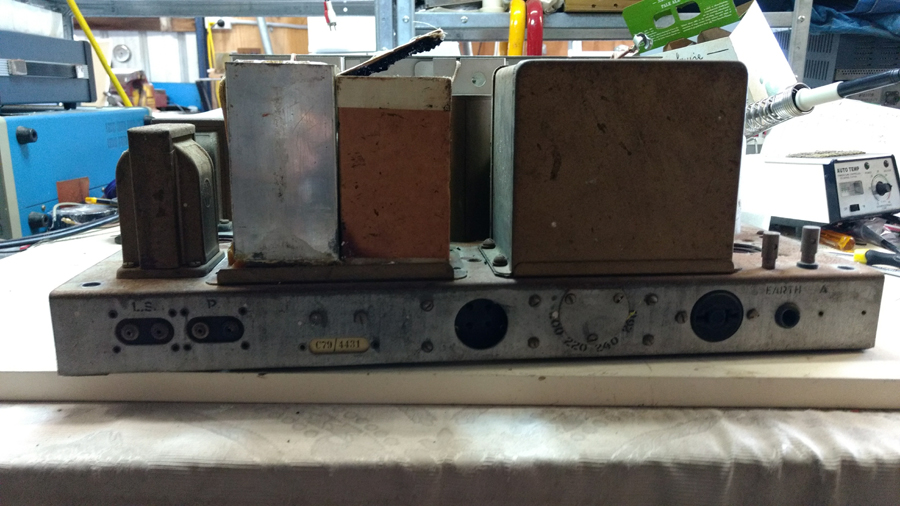 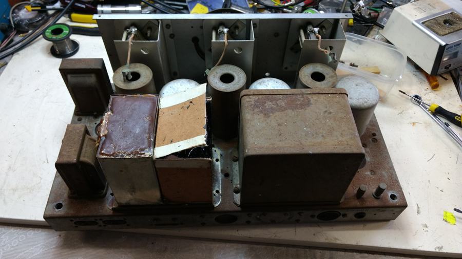 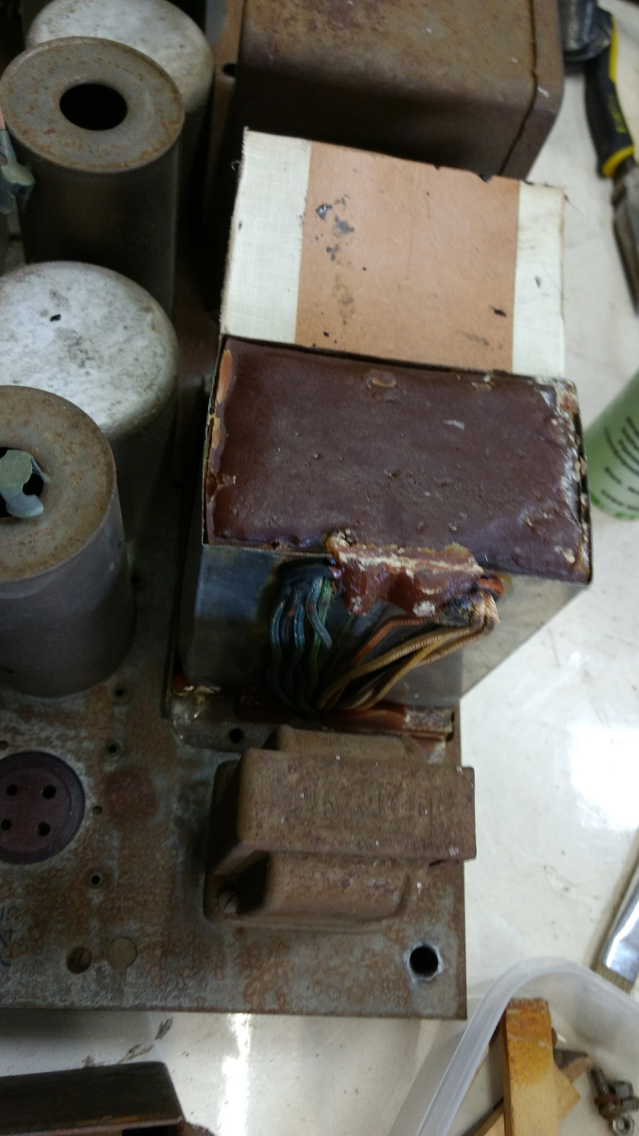 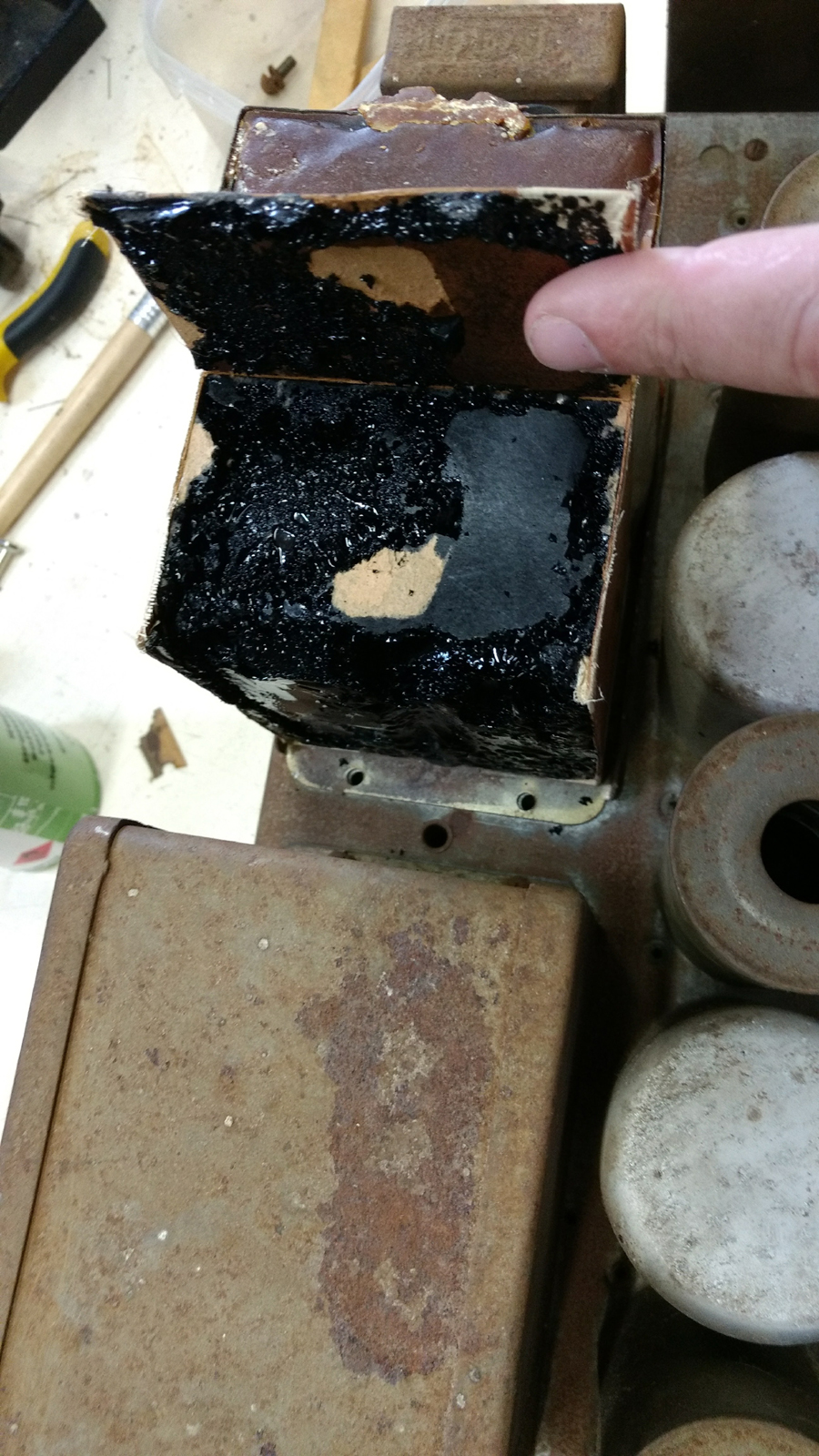 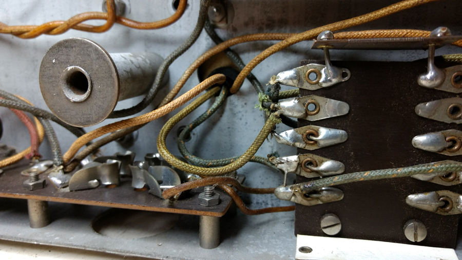 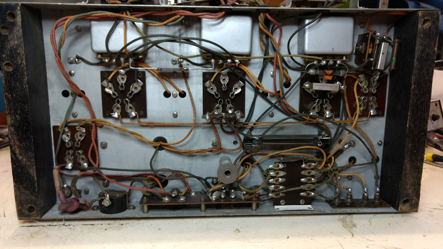 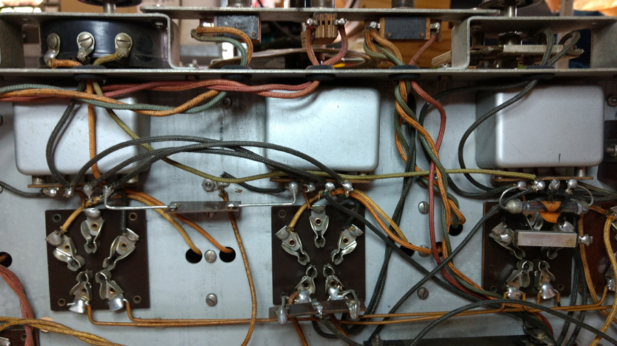 ‾‾‾‾‾‾‾‾‾‾‾‾‾‾‾‾‾‾‾‾‾‾‾‾‾‾‾‾‾‾‾‾‾‾‾‾‾‾‾‾‾‾‾‾‾‾‾‾‾‾‾‾‾‾‾‾‾‾‾‾‾‾‾‾‾‾‾‾ Valve radios, They just don't make them like they used to |
|
|
Return to top of page · Post #: 10 · Written at 3:56:26 PM on 23 October 2017.
|
|
|
|
Location: Wangaratta, VIC
Member since 21 February 2009 Member #: 438 Postcount: 5715 |
|
Do not forget my comment on induction between caps. I normally line those cans with insulation. If you dare to use silicon use the non acid roof & gutter type. Frowned on by some but it makes a wonderful binder & space filler. Just keep it off the wires, some of it can conduct. |
|
|
Return to top of page · Post #: 11 · Written at 6:05:22 PM on 23 October 2017.
|
|
|
|
Location: Adelaide, SA
Member since 27 February 2010 Member #: 630 Postcount: 398 |
|
Explanation of Photos ‾‾‾‾‾‾‾‾‾‾‾‾‾‾‾‾‾‾‾‾‾‾‾‾‾‾‾‾‾‾‾‾‾‾‾‾‾‾‾‾‾‾‾‾‾‾‾‾‾‾‾‾‾‾‾‾‾‾‾‾‾‾‾‾‾‾‾‾ Valve radios, They just don't make them like they used to |
|
|
Return to top of page · Post #: 12 · Written at 10:05:44 PM on 24 October 2017.
|
|

|
Administrator
Location: Naremburn, NSW
Member since 15 November 2005 Member #: 1 Postcount: 7624 |
|
Photo 1 uploaded to OP. Photos 2-8 uploaded to Post 9. ‾‾‾‾‾‾‾‾‾‾‾‾‾‾‾‾‾‾‾‾‾‾‾‾‾‾‾‾‾‾‾‾‾‾‾‾‾‾‾‾‾‾‾‾‾‾‾‾‾‾‾‾‾‾‾‾‾‾‾‾‾‾‾‾‾‾‾‾ A valve a day keeps the transistor away... |
|
|
Return to top of page · Post #: 13 · Written at 10:19:04 PM on 24 October 2017.
|
|
|
|
Location: Adelaide, SA
Member since 27 February 2010 Member #: 630 Postcount: 398 |
|
Thanks Brad. ‾‾‾‾‾‾‾‾‾‾‾‾‾‾‾‾‾‾‾‾‾‾‾‾‾‾‾‾‾‾‾‾‾‾‾‾‾‾‾‾‾‾‾‾‾‾‾‾‾‾‾‾‾‾‾‾‾‾‾‾‾‾‾‾‾‾‾‾ Valve radios, They just don't make them like they used to |
|
|
Return to top of page · Post #: 14 · Written at 10:48:23 AM on 25 October 2017.
|
|
|
|
Location: Toongabbie, NSW
Member since 19 November 2015 Member #: 1828 Postcount: 1407 |
|
Hi Flakes, that is a lovely radio and a real head scratcher as to keeping it original or restoring it completely. |
|
|
Return to top of page · Post #: 15 · Written at 9:04:09 PM on 25 October 2017.
|
|
|
|
Location: Brunswick, VIC
Member since 3 May 2017 Member #: 2100 Postcount: 43 |
|
Hi Flakes, I must say that is a lovely radio and you are right to leave it as much alone as possible. One product that I have used in similar cases that is not petroleum based that is great for stabilising rust is Lanox. It is a Lanolin spray made by Inox. I think most of the auto stores sell it. |
|
|
You need to be a member to post comments on this forum.
|
|


Sign In
Vintage Radio and Television is proudly brought to you by an era where things were built with pride and made to last.
DISCLAIMER: Valve radios and televisions contain voltages that can deliver lethal shocks. You should not attempt to work on a valve radio or other electrical appliances unless you know exactly what you are doing and have gained some experience with electronics and working around high voltages. The owner, administrators and staff of Vintage Radio & Television will accept no liability for any damage, injury or loss of life that comes as a result of your use or mis-use of information on this website. Please read our Safety Warning before using this website.
WARNING: Under no circumstances should you ever apply power to a vintage radio, television or other electrical appliance you have acquired without first having it checked and serviced by an experienced person. Also, at no time should any appliance be connected to an electricity supply if the power cord is damaged. If in doubt, do not apply power.
Shintara - Keepin' It Real · VileSilencer - Maintain The Rage