|
Taylor Vave Tester 45C - settings error for 6AR7GT
|
|
|
|
|

|
Location: NSW
Member since 10 June 2010
Member #: 681
Postcount: 1407
|
If when setting up the tester for the 6AR7GT for testing you don't twig that there might be something wrong when the valve is described as American, as a triode with a diode and rectifier, requires 200V on the screen grid, has no top cap and that the valve does not warm up, you will defintely twig if you happen to brush the lead external shield because you will find that it has a couple of hundred volts DC on it, if you use the specified A, B and C switch settings of 0, 7 and 7.
In fact the 6AR7GT was designed and manufactured in Australia by Amalgamated Wireless Valve (AWV) affiliated with Amalgamated Wireless Australia (AWA) and is branded Radiotron. And it is a duo-diode pentode, and requires 100 volts on the screen grid. And it does have a top cap (for the grid).
Now switch A controls the circuits connected to pins 3 (plate) and 4 (screen grid), and at position 0 this is the cathode for both pins. So both are at at cahode potential, ie grounded so thats not going to work.
Switch B controls the circuits connected to pin 1 (heater) and pin 6 (diode 1), and at position 7 this is grid for pin 1 (heater) and cathode for pin 6 (diode 1). That's not going to work either though it doesn't matter if the diode is grounded if the pentode section is being tested.
Switch C controls the circuits connected to pin 5 (base shield and external shield) and pin 5 (diode 2), and at position 7 this is anode for pin 5 (shields) and cathode for pin 5 (diode 2). So now we know why you get zapped by the external shield!
The correct switch settings for A, B and C are 3, 0 and 0 which connects the correct circuits to the correct pins. This can be worked out with some head scratching by following the procedure in the manual. The B setting could be 15, 16, or 17, the difference being that 0 connects heater and diode 1 to cathode, whereas 15, 16 and 17 leave them unconnected and floating; doesn't appear to affect mutual conductance readings.
The settings of 200 for diode 1 (described as diode) and 004 diode 2 (described as rectifier) appear to be correct; at least responses from the meter are obtained.
So the bottom line is the following changes need to be made to the settings for the 6AR7GT:
``````````````Make``````H/L No.``Base```Heater```````````````Type````````````````Anode, Screen```Cap```Selector```Mutual
```````````````````````````````````````````````````Volts`````````````````````````````````````` and Grid Volts`````````````A, B, C`````Cond.
present:`````USA````````13````````IO2 `````6.3```````Triode/Diode/Rect.````````250, 200, 2```````- ```````0 7 7`````````1.0
change:`Australia`````13````````IO2``````6.3````Tetrode/Diode 1/Diode 2``` 200, 100, 2``````G```````3 0 0`````````1.0
In fact the mutual conductance reading I obtained was 1.2, so that might be worth noting as these valves are somewhat rare.
Note: The formatting of the correction table has been modified on posting, with apparently unnecessary spaces being removed. I'll have a go at fixing this tomorrow.
Note 2: Have replaced spaces with left quote symbol so that the table can be read. Will now try to replace these with bold spaces seeing as I can now more easily count up the spaces needed.
|
|
|
|
|
|
|
Location: NSW
Member since 10 June 2010
Member #: 681
Postcount: 1407
|
Bold spaces didn't work through the edit box for the above post; they were stripped out again on posting.So the corrections are here.
Make H/L No. Base Heater Type Anode, Screen Cap Mutual
Volts and Grid Volts Conductance
present: USA 13 IO2 6.3 Triode/Diode/Rect. 250, 200, 2 - 1.0
change to: Australia 13 IO2 6.3 Tetrode/Diode 1Diode 2 200, 100, 2 G 1.0
Note: Well that didn't work either, so I'll scan and submit present and changed settings and submit them to Brad.
|
|
|
|
|
|
|
Location: NSW
Member since 10 June 2010
Member #: 681
Postcount: 1407
|
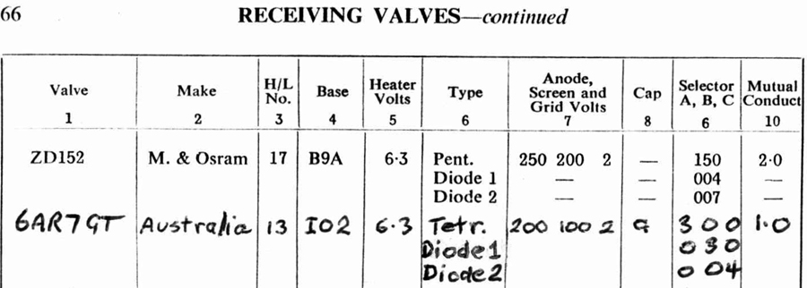
The complete replacement table for the 6AR7GT, including A, B, and C switch positions for Diodes 1 and 2, is:
``````````````Make``````H/L No.``Base```Heater```````````````Type````````````````Anode, Screen```Cap```Selector```Mutual
```````````````````````````````````````````````````Volts`````````````````````````````````````` and Grid Volts`````````````A, B, C`````Cond.
present:`````USA````````13````````IO2 `````6.3`````````````````Triode````````````````250, 200, 2```````- ```````````0 7 7`````````1.0
``````````````````````````````````````````````````````````````````````````Diode````````````````````````````````````````````````2 0 0
```````````````````````````````````````````````````````````````````````````Rect.````````````````````````````````````````````````0 0 4
change:`Australia`````13````````IO2``````6.3`````````````````Tetrode````````````````200, 100, 2```````G`````````3 0 0`````````1.0
`````````````````````````````````````````````````````````````````````````Diode 1``````````````````````````````````````````````0 3 0
`````````````````````````````````````````````````````````````````````````Diode 2``````````````````````````````````````````````0 0 4
Note the change to switch positions for Diode 1 compared to those mentioned in Post 1.
|
|
|
|
|
|
|
Location: NSW
Member since 10 June 2010
Member #: 681
Postcount: 1407
|
Have scanned the existing and changed valve tester manual settings for the 6AR7GT using the Taylor 45C valve tester.
The first is struck out with an annotation "refer p 63". The second is written in at the end of the receiving valve section on page 66.
Will submit these to Brad for consideration for insertion in this post.
|
|
|
|
|

|
Location: Wangaratta, VIC
Member since 21 February 2009
Member #: 438
Postcount: 5715
|
Do be aware that 6AR7 does not follow standard pin-outs for an octal. Most, other than some rectifiers, use pins 2 & 7 as heaters 6AR7 does not: It uses 1 & 8
That is a trap for the ancient VCT, where an adapter has to be made & some Philips valves are the same.
Beware.
|
|
|
|
|

|
Administrator
Location: Naremburn, NSW
Member since 15 November 2005
Member #: 1
Postcount: 7624
|
Documents have been uploaded.
These forums are set to "justify" text so that there is alignment on both the left and right side of the table. This has one unfortunate aspect, text cannot be formatted outside what this function would permit.
There is one undocumented function that will over-ride it. Basically, surround the original text you wanted in CODE tags - EG: [code] and [/code]. These tags were originally intended for a forum I ran about fifteen years ago that included discussions about computer code. These tags over-ride the text justify function so the code appears in its correct format and remains readable. With this though, you still need to play with the space bar a little. The TAB key is used when indenting computer code but this key doesn't work in textboxes.
‾‾‾‾‾‾‾‾‾‾‾‾‾‾‾‾‾‾‾‾‾‾‾‾‾‾‾‾‾‾‾‾‾‾‾‾‾‾‾‾‾‾‾‾‾‾‾‾‾‾‾‾‾‾‾‾‾‾‾‾‾‾‾‾‾‾‾‾
A valve a day keeps the transistor away...
|
|
|
|
|
|
|
Location: NSW
Member since 10 June 2010
Member #: 681
Postcount: 1407
|
"surround the original text you wanted in CODE tags"
I guess this means take out the square bracket b square bracket and square bracket /b square bracket coding but leave in the spaces, and surround each line of the table with square bracket code square bracket and square bracket /code square bracket.
Such an instruction might be handy for members who want to include a table with extra spaces for formatting.
I only persisted with putting in the table in this way because my scanner wasn't available, and to get the information up for other users of Taylor 45s of which a few have popped up over the years, and to avoid relatively rare 6AR7GTs being chucked out on the strength of false test results.
|
|
|
|
|

|
Location: Hobart, TAS
Member since 31 July 2016
Member #: 1959
Postcount: 605
|
Thanks STC830, when I get a chance will fire up my Taylor and a 6AR7 and check it all out.
When I recently got my Taylor it came with no paper work and I have spent considerable time in collecting data sheets, mostly from the net.
Cheers, JJ
|
|
|
|
|
|
|
Location: NSW
Member since 10 June 2010
Member #: 681
Postcount: 1407
|
Just for the record, the serial number of my tester is 330119.
Most of my data is from the net also, though originally I think I got the manual and valve data books from HRSA.
Many traps from errors in valve data and a number of versions of the 45C all of which differed slightly which means that you always need to be suspicious of the documentation especially if it didn't come with the tester.
I have had to make repairs to the ABC selector and Filament Volts switches, due to cracks in the plastic components, and in one case collapse of the plastic holding the detent balls. In this case they were drilled out and brass tubes from BB connectors glued in as they had the same inside diameter as the balls. Very fiddly and if it happens again I would be tempted to chuck it over the back fence!
I have also replaced the selenium rectifiers due to inaccurate voltage readings especially on the grid. The grid volts are closer to the dial because of this but I take the precaution of checking grid volts with a meter. This replacement needs to be done carefully as wrong connections could result in wrong phasing upon which the tests depend (see the manual for how the tester works).
|
|
|
|
|
|
|
Location: Wangaratta, VIC
Member since 21 February 2009
Member #: 438
Postcount: 5715
|
"Franks Electron Tube Pages" http://www.tubedata.info/ has a hell of a lot of valve data sheets.
Interesting with volts The VCT has tappings to compensate & a switch position just for compensating for different line voltages.
|
|
|
|
|
|
|
Location: NSW
Member since 10 June 2010
Member #: 681
Postcount: 1407
|
"valve data"
When I refer to valve data in paras 2 &3 of post 9 I should have said tester switch settings for individual valves.
Taylor do not indicate on the various versions of the 45C manual what tester serial numbers the manual refers to. Radiomuseum members have been building up a database of serial number v manual version for those contributors who have the original manual for their tester. I don't know if this has been finally resolved as I haven't joined that organisation.
The only possible indication that I have for my manual is that it appears to have all of the right valve sockets. I have been able to test all the valves I have put to it except the 6AR7GT and a Philips indicator valve which has extra internal connections, done evidently to facilitate radio wiring and reduce their costs. Unfortunately the tester let the smoke out on testing this valve, but no damage inflicted that I can see to either valve or tester luckily. There is a warning in the manual that valves with non-standard internal connection may not be testable. Hence the importance of the internal shorts test which may show up such valves.
|
|
|
|
|
|
|
Location: Wangaratta, VIC
Member since 21 February 2009
Member #: 438
Postcount: 5715
|
This is a similar issue to what one has with the ancient VCT. Many valves were built after it & whilst some just changed bases, there was not a switching system & in both cases it is a compromise.
In reality the only way to build those things & some have, is have every pin in every socket connected pins 1, 2, 3........... to individual switches that allow a pin to source what it needs & that's where the money goes.
Making a voltage regulator for multiple B voltage is simple an LR8 with TIP50 can make a stepping one.
What often has to happen is to see if you can find another valve with the same pin-outs that is listed. Eg #57 & #58 have the same heater voltage & element pinouts.
|
|
|
|
|
|
|
Location: NSW
Member since 10 June 2010
Member #: 681
Postcount: 1407
|
Taylor have simplified the switching to three switches for selecting circuits for the various valve elements, Anode, Cathode, Grid and Screen. They have done this by having each switch position select two such circuits for the A and B switches three for the C switch. Then there are extra non- selectable circuits that are permanently attached to the cathode, cathode side of filament and filament (later versions of the 45C rearrange this slightly and add extra circuits permanently attached to grid and cathode - hence the problem of knowing exactly which version you have).
To to work out a valve's settings there is a table called the Wiring Chart which tells you which of the 7 selectable circuits your valve pins are on; and which gives various combinations of circuits that are available for each of those pins.
So for the 6AR7GT which has an IO2 socket
circuit 1 is on pin 3, anode. Switch A connects pins 3 & 4, so select position that connects anode and screen. This is position 3, A and S.
circuit 2 is on pin 4, screen grid
circuit 3 is on pin 1, heater, cathode side. Switch B connects pins 1 & 6, this is posn 0, C and C, diode 1 also on C and tested separately
circuit 4 is on pin 6, diode 1
circuit 5 is on pin 2, shield, metal shell. Switch C connects pins 2 & 5, this is also position 0, shield and diode 2 grounded.
circuit 6 is on pin 5, diode 2
circuit 7 is not connected to a pin
8 on anode, 9 & 10 on heater as previously explained, and grid on the cap.
Just to emphasise how this works, the combinations of valve elements available to switch A positions are:
Circuit 0, C & C; 1, G & A; 2, C & A; 3, A & S; 4, G & S; 5,G & C; 6, C & S; 7, A & C; 8, C & G; 9, S & G; 10, G & -; 11, - & S; 12, - & -; 13, - & G; 14, A & -; 15, 16, 17 unassigned.
Multiple but different selections are available to each switch position of switches B and C. A cunning way of simplifying connections, but it does make a few valves un-testable, especially if they have internal connections.
As for multiple B voltage, a quote of the mutual conductance Principle of Operation gives a idea of the issue involved:
"In this test a choice of anode, screen and grid voltages is provided. These are alternating current except that the grid voltage is prevented from going positive by a small rectifier. The transformer windings are phased so that the anode and screen voltages are in phase while the grid voltage is out of phase. When the anode and screen voltages are positive, therefore the grid voltage is negative and meter current passes. When the anode and screen voltages are negative, the grid voltage is zero and no meter current passes. The inertia of the meter causes it to read steadily although the current through it is intermittent."
So the grid is not regulated by direct current, but negative DC biased AC, and anode and screen are AC. This begs the question, have they used RMS values or peak values or some other value of voltage for the grid voltage. I think that they would have used RMS since if you come along with a new valve, you have to depend on the manufacturer's specified grid voltage to work out the grid setting. I don't have a quality RMS digital meter to work this out. My digital meters are not such meters so I check grid voltage with an analogue meter assuming that this will be closer. As I have mentioned before they are sometimes quite away out with my silicon diode modifications to the grid circuit rectifier. A comment somewhere on the net (or maybe here) has said that where Taylor substituted a germanium diode for the selenium rectifier, no other circuit changes were made.
As for other valves, my first reaction was to search through all of the receiver valves in their settings book for I02 valves that were pentodes and had a cap. These were:
DL21, 303, grid on the cap;
UFG, 300, grid on the cap.
So when I got 300 for the 6AR7GT from my cogitations, I had confidence in the result.
|
|
|
|
|
|
|
Location: NSW
Member since 10 June 2010
Member #: 681
Postcount: 1407
|
A bit more about how the Taylor testers work, and the difficulties in checking the grid voltage when its half-wave.
https://www.vintage-radio.net/forum/showthread.php?t=26555
The nub of the grid voltage issue is:
"Trying to measure the half-wave grid voltage with a DC voltmeter will inevitably give a misleading reading.
As it is half-wave AC, then 10 volts on the control should result in a DC average reading at the grid of around 3.5 volts less the forward drop of the two diodes, so 3 volts would be a near-enough correct reading."
|
|
|
|
|
|
|
Location: NSW
Member since 10 June 2010
Member #: 681
Postcount: 1407
|
For some reason
https://www.vintage-radio.net/forum/showthread.php?t=26555
opens this thread. To get it to go to the British website it is necessary to copy it into the address bar of your browser.
I have also discovered on the net that dirty sliders on the wire-wound variable resistors can cause erratic operation. So will clean these and then see if the 10 volt setting on the grid voltage knob actually does give about 3 volts at the grid.
This puzzles me because it suggests that tester works with peak rather than average voltage, since the setting used is the valve manufacturers recommendation, ie 10 volts. I would have thought that the valve would "see" what the meter "sees" ie about 3 volts.
|
|
|
|
|
|
You need to be a member to post comments on this forum.
|