
Tech Talk
Forum home - Go back to Tech talk
|
Need to know about this ceramic disc capacitor
|
|
|
« Back ·
1 ·
Next »
|
|
|
Return to top of page · Post #: 1 · Written at 5:29:45 PM on 1 October 2017.
|
|
|
|
Location: Adelaide, SA
Member since 17 August 2017 Member #: 2154 Postcount: 10 |
|
I'm refurbishing a Heathkit IG-102 rf signal generator. It uses a number of RMC .02 μF +80-20 Z5U ceramic disc capacitors. Unfortunately a couple are missing from someone's previous mod. It has a green banded top. |
|
|
Return to top of page · Post #: 2 · Written at 8:26:23 PM on 1 October 2017.
|
|

|
Location: Sydney, NSW
Member since 28 January 2011 Member #: 823 Postcount: 6949 |
|
You can still get 0.2μF caps, but they are not common anymore. In the standard series numbering scheme used today, the nearest would be 0.22uF. |
|
|
Return to top of page · Post #: 3 · Written at 12:23:39 AM on 2 October 2017.
|
|
|
|
Location: Adelaide, SA
Member since 17 August 2017 Member #: 2154 Postcount: 10 |
|
A picture of the relevant part of the circuit has been sent for approval as an attachment to this post. 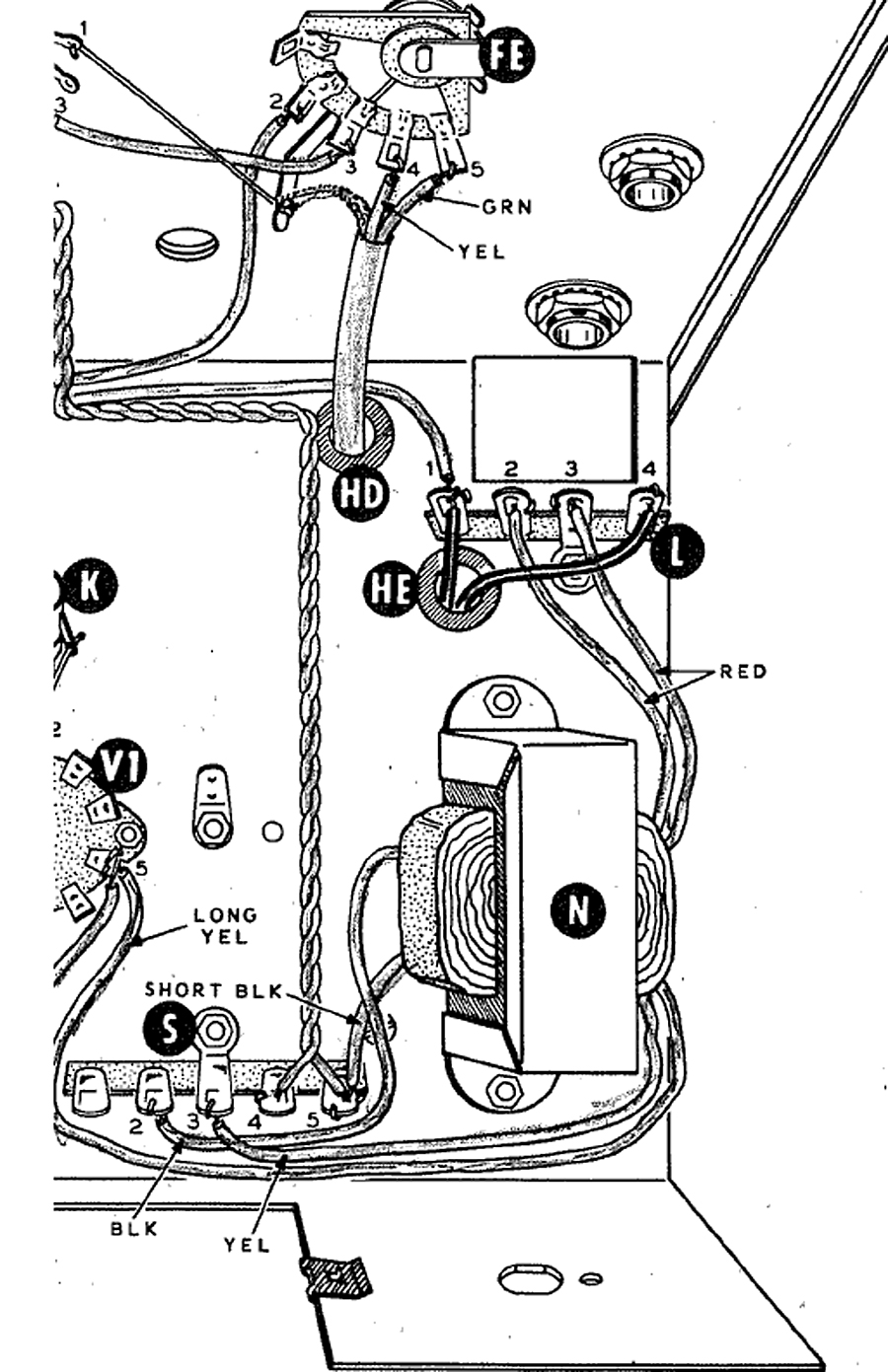 |
|
|
Return to top of page · Post #: 4 · Written at 4:54:13 PM on 2 October 2017.
|
|

|
Administrator
Location: Naremburn, NSW
Member since 15 November 2005 Member #: 1 Postcount: 7624 |
|
Diagram uploaded to Post 3. ‾‾‾‾‾‾‾‾‾‾‾‾‾‾‾‾‾‾‾‾‾‾‾‾‾‾‾‾‾‾‾‾‾‾‾‾‾‾‾‾‾‾‾‾‾‾‾‾‾‾‾‾‾‾‾‾‾‾‾‾‾‾‾‾‾‾‾‾ A valve a day keeps the transistor away... |
|
|
Return to top of page · Post #: 5 · Written at 6:20:01 PM on 2 October 2017.
|
|
|
|
Location: NSW
Member since 10 June 2010 Member #: 681 Postcount: 1407 |
|
Wouldn't it be great to have such diagrams on everything we work on! |
|
|
Return to top of page · Post #: 6 · Written at 7:01:17 PM on 2 October 2017.
|
|
|
|
Location: Sydney, NSW
Member since 28 January 2011 Member #: 823 Postcount: 6949 |
|
The schematic would be more helpful in this case. |
|
|
« Back ·
1 ·
Next »
|
|
|
You need to be a member to post comments on this forum.
|
|
Sign In
Vintage Radio and Television is proudly brought to you by an era where things were built with pride and made to last.
DISCLAIMER: Valve radios and televisions contain voltages that can deliver lethal shocks. You should not attempt to work on a valve radio or other electrical appliances unless you know exactly what you are doing and have gained some experience with electronics and working around high voltages. The owner, administrators and staff of Vintage Radio & Television will accept no liability for any damage, injury or loss of life that comes as a result of your use or mis-use of information on this website. Please read our Safety Warning before using this website.
WARNING: Under no circumstances should you ever apply power to a vintage radio, television or other electrical appliance you have acquired without first having it checked and serviced by an experienced person. Also, at no time should any appliance be connected to an electricity supply if the power cord is damaged. If in doubt, do not apply power.
Shintara - Keepin' It Real · VileSilencer - Maintain The Rage