
Tech Talk
Forum home - Go back to Tech talk
|
LEKMEK 540 1938 Restoration
|
|
|
« Back ·
1 ·
Next »
|
|
|
Return to top of page · Post #: 1 · Written at 7:30:24 PM on 27 July 2017.
|
|
|
|
Location: Clare, SA
Member since 27 March 2016 Member #: 1894 Postcount: 513 |
|
A few photo's of the project so far, I bought this in a sad state, it had been plastered in white paint, so had to be stripped with nasty old paint stripper, then sanded and sanded. Then stained and a coat of varnish. I had trouble with the corners, just couldn't get the traces of white paint out without gouging the veneer, so instead after the first varnish coat, used a tiny brush with brown acrylic craft paint to dab into the corners. All to do now is a couple more coats with a light sand in between. how many I'm not sure, will appraise as I go. I used Cabot's Cabothane for this, it seems to be giving me a really good finish. The chassis suffered from a burnt out candohm, open between each section. A donor to who I am very grateful to, sent me another which I have fitted, until I find a 425 ohm 5 watt resistor I have 3 one watter's patched in parallel giving me 400 ohms, so in the ball park and now the radio is working and I have the correct voltages at the candohm taps, but my HT is still 40 odd volts too high 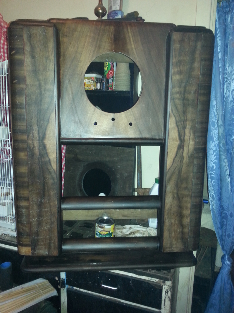 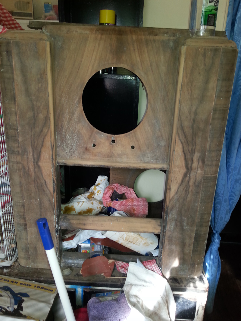 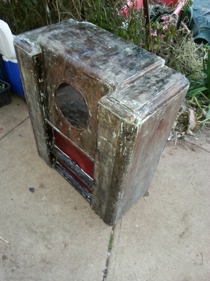 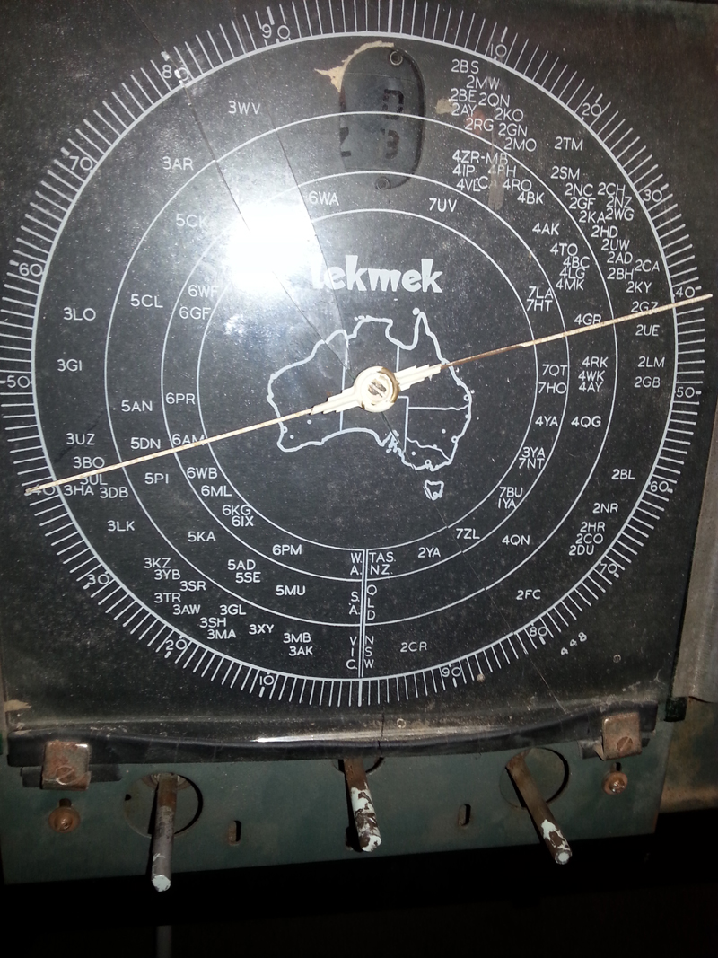 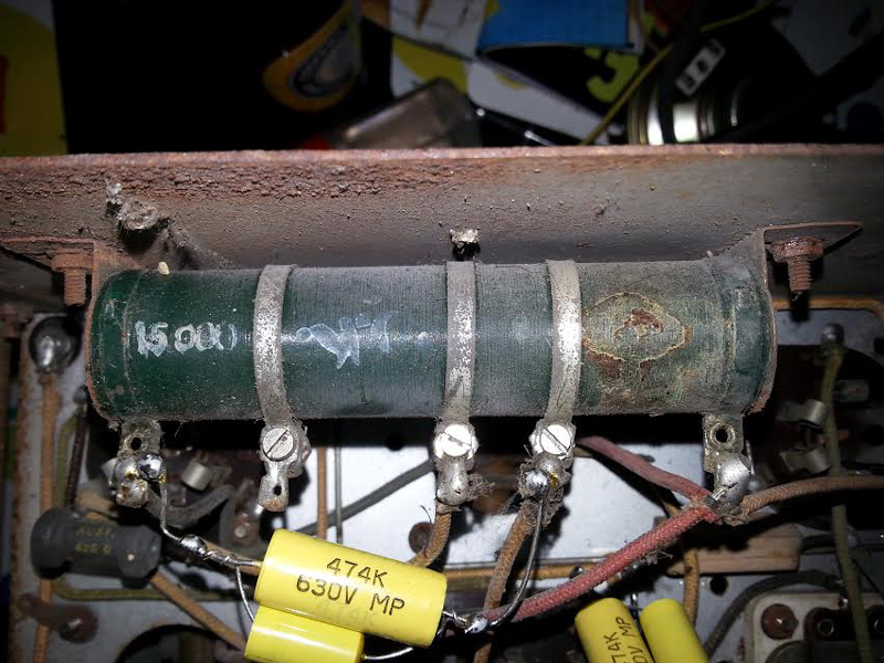 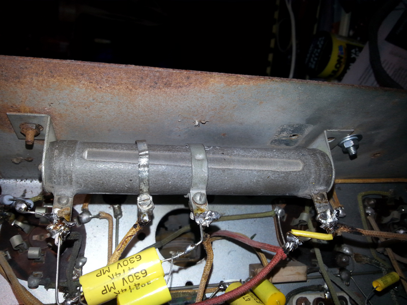 |
|
|
Return to top of page · Post #: 2 · Written at 9:57:22 PM on 27 July 2017.
|
|

|
Administrator
Location: Naremburn, NSW
Member since 15 November 2005 Member #: 1 Postcount: 7624 |
|
Photos uploaded. ‾‾‾‾‾‾‾‾‾‾‾‾‾‾‾‾‾‾‾‾‾‾‾‾‾‾‾‾‾‾‾‾‾‾‾‾‾‾‾‾‾‾‾‾‾‾‾‾‾‾‾‾‾‾‾‾‾‾‾‾‾‾‾‾‾‾‾‾ A valve a day keeps the transistor away... |
|
|
Return to top of page · Post #: 3 · Written at 9:58:26 PM on 27 July 2017.
|
|

|
Location: Albury, NSW
Member since 1 May 2016 Member #: 1919 Postcount: 2048 |
|
Hi Jamie, |
|
|
Return to top of page · Post #: 4 · Written at 11:01:43 PM on 27 July 2017.
|
|

|
Location: Latham, ACT
Member since 21 February 2015 Member #: 1705 Postcount: 2231 |
|
One thing I would like to ask is how do Candohm resisters work? I mean to say that it looks like its a continuous winding with metal clamps at certain gaps, are the windings actually connected to the clamps via solder or are they just clamped and thats it . I have never pulled one apart to see . I do understand how the resistance is divided . |
|
|
Return to top of page · Post #: 5 · Written at 11:41:59 PM on 27 July 2017.
|
|
|
|
Administrator
Location: Naremburn, NSW
Member since 15 November 2005 Member #: 1 Postcount: 7624 |
|
They were very commonplace in Australian 1930s receivers. No solder was used on the clamps, aside from terminations. They are just like hose clamps and touch the winding in just the right spot. Some were made of bare resistance wire on a fibre former and others had a coating on them to help prevent corrosion. ‾‾‾‾‾‾‾‾‾‾‾‾‾‾‾‾‾‾‾‾‾‾‾‾‾‾‾‾‾‾‾‾‾‾‾‾‾‾‾‾‾‾‾‾‾‾‾‾‾‾‾‾‾‾‾‾‾‾‾‾‾‾‾‾‾‾‾‾ A valve a day keeps the transistor away... |
|
|
Return to top of page · Post #: 6 · Written at 12:36:59 AM on 28 July 2017.
|
|

|
Location: Wangaratta, VIC
Member since 21 February 2009 Member #: 438 Postcount: 5715 |
|
Those were actually used as a voltage divider. Some were a continuous 15K others 25K. One end B- the other B+. |
|
|
Return to top of page · Post #: 7 · Written at 9:00:36 AM on 28 July 2017.
|
|

|
Location: Sydney, NSW
Member since 28 January 2011 Member #: 823 Postcount: 6949 |
|
Great work on the cabinet there, Jamie. A lot of effort indeed, but looks like it's paying off. |
|
|
Return to top of page · Post #: 8 · Written at 5:51:55 PM on 28 July 2017.
|
|
|
|
Location: Clare, SA
Member since 27 March 2016 Member #: 1894 Postcount: 513 |
|
Yeah that's my first coat, I'm up to five now, with a light 400 grit sand in between! Each time it dry's I notice a couple of runs or a bristle stuck in it, but I'm aiming for seven coats, but it'll get whatever it needs really. Yes I used Oak stain on the sides and the centre around the speaker area on what you'd call the head, foot, transoms and mullions, (using window terminology) also the flat bits between the very top and sides, however the top and front facings have no stain, just the wood which appears to be real English oak ply. It is actually a very attractive cabinet, why some nutter would plaster it with white paint is beyond me, but there was a "white paint" period in the mid to later 20th century where lunatics desecrated anything they could with the stuff?!?! |
|
|
« Back ·
1 ·
Next »
|
|
|
You need to be a member to post comments on this forum.
|
|
 265 volts which should be about 225? Something to figure out, but the HT comes straight from the 80 rectifier via the speaker field coil, strangely there are 3 wires coming out of the speaker going nowhere and only when two of these are joined will the speaker voice coil have continuity so maybe there was something wired in series with the voice coil? If anybody has or knows of anybody with a Lekmek 540, I'd like to talk with you! In any case the radio is working fine and I can't see the extra 40 volts causing any greif, I'm just going to have to power it up and watch for an hour or two before assembling it. One resistor reading 5,900 ohm should be 5,000, so that might have a bearing on the high voltage, that's my next job, then finding a new dial glass if I can, there is a bloke I believe who makes these. Coming along nicely!!!
Sign In
Vintage Radio and Television is proudly brought to you by an era where things were built with pride and made to last.
DISCLAIMER: Valve radios and televisions contain voltages that can deliver lethal shocks. You should not attempt to work on a valve radio or other electrical appliances unless you know exactly what you are doing and have gained some experience with electronics and working around high voltages. The owner, administrators and staff of Vintage Radio & Television will accept no liability for any damage, injury or loss of life that comes as a result of your use or mis-use of information on this website. Please read our Safety Warning before using this website.
WARNING: Under no circumstances should you ever apply power to a vintage radio, television or other electrical appliance you have acquired without first having it checked and serviced by an experienced person. Also, at no time should any appliance be connected to an electricity supply if the power cord is damaged. If in doubt, do not apply power.
Shintara - Keepin' It Real · VileSilencer - Maintain The Rage