Welcome to Australia's only Vintage Radio and Television discussion forums. You are not logged in. Please log in below, apply for an account or retrieve your password.
Australian Vintage Radio Forums
  Home  ·  About Us  ·  Discussion Forums  ·  Glossary  ·  Outside Links  ·  Policies  ·  Services Directory  ·  Safety Warnings  ·  Tutorials

Tech Talk

Forum home - Go back to Tech talk

 STC Model 562 Restoration Chassis.
« Back · 1 · 2 · 3 · 4 · Next »
 Return to top of page · Post #: 1 · Written at 12:57:37 PM on 1 July 2017.
Captgogo's Gravatar
 Location: Sydney, NSW
 Member since 22 May 2017
 Member #: 2114
 Postcount: 120

Hi All
After finishing the Cabinet Restoration thanks to Vintage Pete for his detailed advise and special thanks to Ian Robertson for the Speaker Grill Cloth.
I have now found some time to start on the Chassis, so photos will follow thanks Brad. (Please remember I am new to this sorry sorry if I ask silly questions.)
The valve no. on three where legible but two which I am assuming are the same type, being both branded Brimar from the USA, one of these I could just see the 5 and guessing 7 so a 57 valve type, which would make sense that both these are 57s and correspond to the model 562 Chassis schematic from Lankshear article in EA. So if I am right then the only valve that does not match exactly is the Type 83V on my Chassis which I am guessing is similar enough to the 280, V5 in Lanshear's. Any thoughts.
Underneath the Chassis, it appears someone has domes some work on this and possibly replace some capacitors please review photo and would be please to hear your opinions.
So my question is to anyone familiar with this radio and era, what should I do first and the best steps. I am a little concerned that the previous owner who picked this at an auction and did not have any knowledge of radios switch this on to show that it lit up for the photo on ebay. So what damage may have been caused is a concern.
I notice a lot of melted wax goo, not sure if it clear in the photo under the power transformer.
Any advice or tips or things to avoid is welcomed, before I start to consider replacing old components and begin testing.

Thanks George


 Return to top of page · Post #: 2 · Written at 5:12:14 PM on 1 July 2017.
Marcc's avatar
 Location: Wangaratta, VIC
 Member since 21 February 2009
 Member #: 438
 Postcount: 5253

83V has a Cathode sleeve, 80 does not. 80 will produce a voltage surge of around twice the running B voltage until the heaters get the valves to conduct. 83V will not do that to anything like the same extent.

The most common Autodyne, (Screen Grid) combination is 57 pre amp, 58 Autodyne mixer, 57 RF amp & plate detector.562 Normally relates to chassis like 56 which from my info is1934.

57, 58, 57, 2A5, 80 Have circuit for that chassis. On that basis 83V would have to go as it draws 1Amp more filament current & is liable to cook the winding

Marc


 Return to top of page · Post #: 3 · Written at 5:21:01 PM on 2 July 2017.
Captgogo's Gravatar
 Location: Sydney, NSW
 Member since 22 May 2017
 Member #: 2114
 Postcount: 120

Thanks Marc for your reply, I have run the Dim Lamp test, without the Rectifer 83V and then with it, the light remained dim with 75watt lamp. All the other valves also lit up, some static came through the speakers but could not get much response in tring to tune in a station, though only left it on for a short 5 mins to be safe and was cautious of your comment regarding the 83V current rating and I do not have a 280 which is you suggest is the right valve for this circuit. So I intend to try and get the 280 Rectifer once I can source one( any suggestions)
The goo below the transformer which maybe visible when the photos get uploaded, seems to indicate a possible problem with the power tranny, not sure how conclusive the dim lamp test is, so may need to start measuring the voltage at the secondaries to see of they meet spec.
Also interested if any of you review the photos once posted and you if you think the capacitors have already been replaced, also I am assuming the large condensers will need to be replaced as well as any resistors that are no longer in spec.

Are there any other test I should run before getting stuck into reviewing the schematics and measuring the components to determine what parts I need to replace.
George.

STC 562 Console Radio


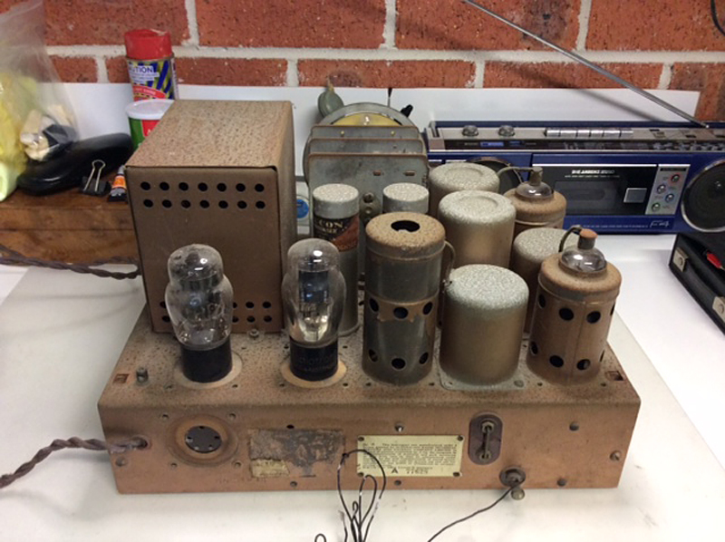
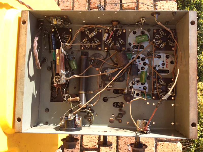
 Return to top of page · Post #: 4 · Written at 5:44:51 PM on 2 July 2017.
Ian Robertson's Gravatar
 Location: Belrose, NSW
 Member since 31 December 2015
 Member #: 1844
 Postcount: 2369

Dim lamp test says your power tranny is probably OK. It might have been caused some slight distress in the past due to the larger rectifier bottle.

Time to start measuring voltages. B+ and cathode, G1, G2 and plate on all valves for a start. List them down while running with a 75 watt bulb in circuit for safety and I can tell you where to go next.

80s are getting rare. New old stock globe-shape 280 is US$79 at tubedepot.com. Lovely and authentic, but do you want to spend that much?

New Sovtek 5Y3GT (same as 80 with an octal base) is US$14.95 from the same source.

I'd be inclined to stick with what you have and check the transformer for heating after about an hour's running. That's after any other issues are sorted.


 Return to top of page · Post #: 5 · Written at 8:33:40 PM on 2 July 2017.
Brad's avatar
 Administrator
 Location: Naremburn, NSW
 Member since 15 November 2005
 Member #: 1
 Postcount: 7300

Photos uploaded to Post 3.


‾‾‾‾‾‾‾‾‾‾‾‾‾‾‾‾‾‾‾‾‾‾‾‾‾‾‾‾‾‾‾‾‾‾‾‾‾‾‾‾‾‾‾‾‾‾‾‾‾‾‾‾‾‾‾‾‾‾‾‾‾‾‾‾‾‾‾‾
A valve a day keeps the transistor away...

 
 Return to top of page · Post #: 6 · Written at 9:54:13 PM on 2 July 2017.
Marcc's avatar
 Location: Wangaratta, VIC
 Member since 21 February 2009
 Member #: 438
 Postcount: 5253

A couple of concerns.

What is the voltage rating of those Black filter caps?

I do not like the mains cable, its probably cloth rubber. & its anchoring leaves a lot to be desired.

Some of those wires with eroded ends or are bare, look like they can get into mischief.

Make sure those chassis mount caps are disconnected. That aerial wire with the tape on it & its mate are tatty. Cloth coavered wire is available.

Green coloured caps, these are modern, green ones are normally 100V what are they?

Marc


 Return to top of page · Post #: 7 · Written at 8:15:52 AM on 3 July 2017.
Captgogo's Gravatar
 Location: Sydney, NSW
 Member since 22 May 2017
 Member #: 2114
 Postcount: 120

Thanks Ian and Marc, I will proceed with further inspection and measurement of the. Valve voltages, I will also check out the voltage rating of the black filter caps and get back to you.
Agree Marc, when I first looked under this , even to my limited experience this looked like a bit tardy and that someone had certainly done some work on this.
I will look to replace the power cord which is not in that bad a condition is unusually very long, so I might be able to cut off the area where the cloth has deteriorated one small area near the radio and reuse it or is it a bad idea to reuse this cloth rubber cord due to its age. Though take your point ans will better secure the cord.

You suggested disconecting the large 2 Chasis mounted caps, is this before I proceed to test the valve voltages?

George


 Return to top of page · Post #: 8 · Written at 8:27:18 AM on 3 July 2017.
Vintage Pete's avatar
 Location: Albury, NSW
 Member since 1 May 2016
 Member #: 1919
 Postcount: 2048

George,
You can buy Repo cloth cord on ebay and a few other places if that appeals to you.......
Pete


 Return to top of page · Post #: 9 · Written at 9:14:02 AM on 3 July 2017.
Marcc's avatar
 Location: Wangaratta, VIC
 Member since 21 February 2009
 Member #: 438
 Postcount: 5253

Repo cords with three wires are common & used in lighting. I think I have seen Steve advertising them? My concern is with the old rubber, it often rots, or goes brittle & cracks and can start a fire.

Relative to commercial repairs, I have "tag & test" and see plenty of dodgy cables. Actually had a (sealed plugs) caravan one recently with no earth continuity (scary). Pre RCD I did see a deceased Possum leave a caravan with only Active: Hence the risk assessment.

As there are obvious new Electrolytic's in that set paralleling them is lazy & bad form. It can lessen the life of a rectifier by stripping the cathode and if it has lost "form" it is liable to present as a short, & I saw the ramifications of someone doing that, recently.

Did you end up with a circuit for it? Kevin Chant may have & I have.

Marc


 Return to top of page · Post #: 10 · Written at 9:44:38 AM on 3 July 2017.
Fred Lever's Gravatar
 Location: Toongabbie, NSW
 Member since 19 November 2015
 Member #: 1828
 Postcount: 1250

Hi George, the power cord is a fright and needs removing and putting in the bin.
The set needs a cord with an EARTH wire to properly earth the metal chassis for safety.
Better than nothing, the earth wire could be soldered to a solder lug bolted under a chassis nut although an earth lug is supposed to have its own single purpose hole with cleaned bright steel and bolt. There should be a cord clamp included to take the strain.
I would fit a chassis gland and drill a hole for the earth lug but that may make the thing non standard in some peoples eyes.

Re the look of the chassis you either lightly chemically treat the grime and rust to clean it and leave it at with 'natural patina' or strip it to the last nut and bolt and re-do the steel work from scratch.
As its your first 'refurb' I would just clean it up. I have done that to a couple of chassis and they look quite neat especially where I have repainted some of the detachable parts like the valve shields and covers with spray to match the basic chassis colour.
If you want to frighten yourself look at my Kriesler 3-k15 rebuild in the special projects section on this site where I go the whole hog.
Whatever you do DONT just slop silver paint over the rust to make it look pretty ( awful) like some I have seen.
Have a look at some of my refurbs in special projects and you will see various levels of work and the effects on the look of the set chassis.

Dont take any notice of what I do with woodwork being a complete clod in that respect, Pete is the go to man and guys like Ian and Marc have good handle on the electronics.
To me that chassis is a little ripper being simple but yes the repair guys have been there and a lot of those little caps are new and I too would be concerned at the voltage rating of some of them.
Love the 'rats nest' wiring if you touch it it will crack and split!
I would just fix whats crook and tidy the rest.

Nice project.

Fred.


 Return to top of page · Post #: 11 · Written at 10:50:55 AM on 3 July 2017.
Captgogo's Gravatar
 Location: Sydney, NSW
 Member since 22 May 2017
 Member #: 2114
 Postcount: 120

Ok so I had a little time to quickly inspect the caps and the 2 Black one in series are rate 500V and 16 μF, and the green ones are rate 650v. These cap ratings should be ok or do I need to consider replacing these?
On close inspection it appears the large Chasis mounted Caps have been already disconnected.
I may have to spend some fun time tracing out this circuit and compare it to the orginal 562 available to see what mods may have been done and the implications.

Thank for you advice Fred, and I will certainly replace the cord wnd include a solid ground to the Chasis.
I have in fact looked a your projects and was in awe of what you have done and the level of work youut into these radios, wow it must certainly be a labour of love and you seem a jack of all trades very impressive workshop you must have.

If I find some time over the next few days I will check all the valve pin voltage and come back to you Ian.

Cheers George


 Return to top of page · Post #: 12 · Written at 11:03:38 AM on 3 July 2017.
Captgogo's Gravatar
 Location: Sydney, NSW
 Member since 22 May 2017
 Member #: 2114
 Postcount: 120

Marc,
I have a circuit diagram from the EA article on the STC 1 restoration from Lankshear"s article, though it does not provide any component values. If you have a better one, I could certainly use It.
Do you think I should replace those black caps in series with a single one?
George


 Return to top of page · Post #: 13 · Written at 11:23:42 AM on 3 July 2017.
Ian Robertson's Gravatar
 Location: Belrose, NSW
 Member since 31 December 2015
 Member #: 1844
 Postcount: 2369

Hey George, don't replace anything except the power cord until you measure those voltages. Save yourself a lot of trouble!

I'll see if I can find you a circuit.

YES! On Kevin Chant's site:

http://www.kevinchant.com/stc2.html

It's down the bottom, "59E Mods .tif"

It doesn't have the pinouts for the valves but you can get those elsewhere.

I am very confident that this is your chassis.


 Return to top of page · Post #: 14 · Written at 12:50:32 PM on 3 July 2017.
Ian Robertson's Gravatar
 Location: Belrose, NSW
 Member since 31 December 2015
 Member #: 1844
 Postcount: 2369

George, in case you didn't know, this site is a good place to get valve data sheets - the 2A5 is on this page:

https://frank.pocnet.net/sheets21.html

Also in case you didn't know, pin numbers are shown looking underneath the chassis, starting with the heater pins, which for UX series valves are the thicker ones.

With the heater pins facing you, the left-hand heater pin is pin 1. Go anticlockwise from there.


 Return to top of page · Post #: 15 · Written at 1:38:43 PM on 3 July 2017.
Captgogo's Gravatar
 Location: Sydney, NSW
 Member since 22 May 2017
 Member #: 2114
 Postcount: 120

Ian,
I had another look on Kevin Chants site, as initially when I looked I was looking for 56 not 59, I agree that this looks like the circuit.
I managed to measure the heater voltages, on the 83V it was quite high, P1 250V and P4 400V ? P2 200V and P3 195V

On the other valve heaters, I was getting about 0.8 to 1.1V for each. Do these sound right?
I took all measurement from Common ground to each PIn.

I will now look up each valve and do all the voltage measurements again including the anodes and grids.
Thanks for the links
George


« Back · 1 · 2 · 3 · 4 · Next »
 You need to be a member to post comments on this forum.

Sign In

Username:
Password:
 Keep me logged in.
Do not tick box on a computer with public access.