
Tech Talk
Forum home - Go back to Tech talk
|
32V Power Supply
|
|
|
Return to top of page · Post #: 1 · Written at 8:07:06 PM on 2 May 2017.
|
|

|
Location: Adelaide, SA
Member since 27 February 2010 Member #: 630 Postcount: 398 |
|
Hi All ‾‾‾‾‾‾‾‾‾‾‾‾‾‾‾‾‾‾‾‾‾‾‾‾‾‾‾‾‾‾‾‾‾‾‾‾‾‾‾‾‾‾‾‾‾‾‾‾‾‾‾‾‾‾‾‾‾‾‾‾‾‾‾‾‾‾‾‾ Valve radios, They just don't make them like they used to |
|
|
Return to top of page · Post #: 2 · Written at 10:13:34 PM on 2 May 2017.
|
|

|
Location: Wangaratta, VIC
Member since 21 February 2009 Member #: 438 Postcount: 5715 |
|
What one needs to do is have a hunt to see if you can spot some models that are Vibrator (Operatic) sometimes they bother to tell you the current draw. |
|
|
Return to top of page · Post #: 3 · Written at 6:25:35 AM on 3 May 2017.
|
|
|
|
Location: Oradell, US
Member since 2 April 2010 Member #: 643 Postcount: 839 |
|
Computer printers often use separate power bricks that are around 30VDC. However, they are switching power supplies, and likely will produce RFI into the radio. And you probably need more current than they usually are rated for. |
|
|
Return to top of page · Post #: 4 · Written at 9:43:21 AM on 3 May 2017.
|
|
|
|
Location: Wangaratta, VIC
Member since 21 February 2009 Member #: 438 Postcount: 5715 |
|
Leaving things not running with a PSU that does not need to be running is rather wasteful long term and I don't really consider is desirable, or really necessary to use a regulated supply with such a dirty system as a mechanical vibrator. |
|
|
Return to top of page · Post #: 5 · Written at 10:38:38 AM on 3 May 2017.
|
|
|
|
Location: Belrose, NSW
Member since 31 December 2015 Member #: 1844 Postcount: 2710 |
|
Here's a tested design with suggested component source references. 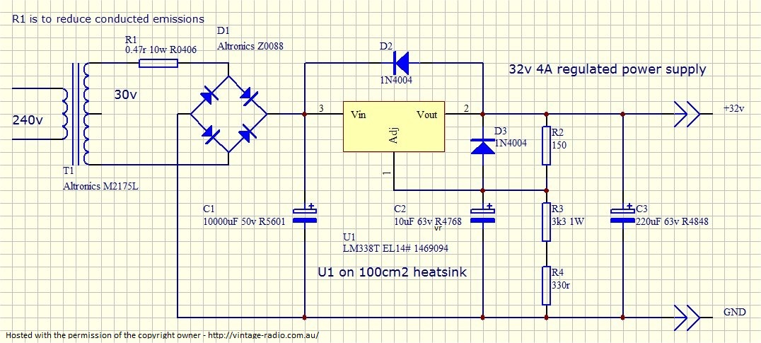 |
|
|
Return to top of page · Post #: 6 · Written at 10:49:02 AM on 3 May 2017.
|
|
|
|
Location: Belrose, NSW
Member since 31 December 2015 Member #: 1844 Postcount: 2710 |
|
I should add a comment about the TO-220 package pinout. |
|
|
Return to top of page · Post #: 7 · Written at 8:13:37 PM on 3 May 2017.
|
|
|
|
Location: Adelaide, SA
Member since 27 February 2010 Member #: 630 Postcount: 398 |
|
Hi Ian ‾‾‾‾‾‾‾‾‾‾‾‾‾‾‾‾‾‾‾‾‾‾‾‾‾‾‾‾‾‾‾‾‾‾‾‾‾‾‾‾‾‾‾‾‾‾‾‾‾‾‾‾‾‾‾‾‾‾‾‾‾‾‾‾‾‾‾‾ Valve radios, They just don't make them like they used to |
|
|
Return to top of page · Post #: 8 · Written at 9:14:41 PM on 3 May 2017.
|
|

|
Administrator
Location: Naremburn, NSW
Member since 15 November 2005 Member #: 1 Postcount: 7624 |
|
Circuit diagram uploaded to Post 5. ‾‾‾‾‾‾‾‾‾‾‾‾‾‾‾‾‾‾‾‾‾‾‾‾‾‾‾‾‾‾‾‾‾‾‾‾‾‾‾‾‾‾‾‾‾‾‾‾‾‾‾‾‾‾‾‾‾‾‾‾‾‾‾‾‾‾‾‾ A valve a day keeps the transistor away... |
|
|
Return to top of page · Post #: 9 · Written at 8:11:25 PM on 4 May 2017.
|
|
|
|
Location: Wangaratta, VIC
Member since 21 February 2009 Member #: 438 Postcount: 5715 |
|
Do not ever overlook the humble CPU fan. I have used more than one in a PSU to keep air moving across heat sinks. One unit I made has a heat sink on the actual board. So the fan went into the base of the vintage looking PSU box and actually blows cold air into the box aimed at the heat sink, cooling everything (Box is of course vented). |
|
|
Return to top of page · Post #: 10 · Written at 1:55:43 PM on 5 May 2017.
|
|
|
|
Location: Belrose, NSW
Member since 31 December 2015 Member #: 1844 Postcount: 2710 |
|
Yes Marc, very useful for smaller heatsinks and if there is no natural airflow. |
|
|
Return to top of page · Post #: 11 · Written at 9:57:06 AM on 6 May 2017.
|
|
|
|
Location: Wangaratta, VIC
Member since 21 February 2009 Member #: 438 Postcount: 5715 |
|
Fans are a great boon in keeping things cool in really hot temperatures. One example I saw was a tube heat sink so everything got moving air. |
|
|
Return to top of page · Post #: 12 · Written at 4:51:30 PM on 6 May 2017.
|
|
|
|
Location: Adelaide, SA
Member since 27 February 2010 Member #: 630 Postcount: 398 |
|
Got sidetracked today trying to align electrically and mechanically a Philips Radioplayer 124 so haven't had a chance to build the power supply. ‾‾‾‾‾‾‾‾‾‾‾‾‾‾‾‾‾‾‾‾‾‾‾‾‾‾‾‾‾‾‾‾‾‾‾‾‾‾‾‾‾‾‾‾‾‾‾‾‾‾‾‾‾‾‾‾‾‾‾‾‾‾‾‾‾‾‾‾ Valve radios, They just don't make them like they used to |
|
|
Return to top of page · Post #: 13 · Written at 11:44:14 PM on 6 May 2017.
|
|
|
|
Location: Wangaratta, VIC
Member since 21 February 2009 Member #: 438 Postcount: 5715 |
|
I don't like the sound of trying? The worst one I have had recently was the 92X Egg Crate, that had been fully adjusted (anything that moved). The IFt's did adjust per plan in seconds. Re-resonating the aerial coil trimmer C3 & fixed cap C1 was annoying but ......That happens (rarely). |
|
|
Return to top of page · Post #: 14 · Written at 2:58:22 PM on 7 May 2017.
|
|
|
|
Location: Adelaide, SA
Member since 27 February 2010 Member #: 630 Postcount: 398 |
|
Well it's 1/2 way through Sunday. All the Trying finally sorted out the Philips. Someone had unsuccessfully replaced the Gang. The Shaft on the Gang was shorter than the original one and the dial string popped off when the baffle board was screwed in the case. I had to "Fix" and then re string both dial and knob strings, IF alignment, Osc alignment, now sounds sweet..... 32V stuff can wait another day. Thanks to Ian for the Circuit. ‾‾‾‾‾‾‾‾‾‾‾‾‾‾‾‾‾‾‾‾‾‾‾‾‾‾‾‾‾‾‾‾‾‾‾‾‾‾‾‾‾‾‾‾‾‾‾‾‾‾‾‾‾‾‾‾‾‾‾‾‾‾‾‾‾‾‾‾ Valve radios, They just don't make them like they used to |
|
|
Return to top of page · Post #: 15 · Written at 10:27:14 AM on 9 May 2017.
|
|
|
|
Location: Belrose, NSW
Member since 31 December 2015 Member #: 1844 Postcount: 2710 |
|
Just thinking, Flakes, your concern about using an unregulated supply is probably unjustified. Cold valve heaters have a lower resistance and will drop the voltage on turn-on until they warm up a bit. You'd probably get away with a brute force R - C filter - adjust the R to get your 32V and add C until the hum stops! |
|
|
You need to be a member to post comments on this forum.
|
|
Sign In
Vintage Radio and Television is proudly brought to you by an era where things were built with pride and made to last.
DISCLAIMER: Valve radios and televisions contain voltages that can deliver lethal shocks. You should not attempt to work on a valve radio or other electrical appliances unless you know exactly what you are doing and have gained some experience with electronics and working around high voltages. The owner, administrators and staff of Vintage Radio & Television will accept no liability for any damage, injury or loss of life that comes as a result of your use or mis-use of information on this website. Please read our Safety Warning before using this website.
WARNING: Under no circumstances should you ever apply power to a vintage radio, television or other electrical appliance you have acquired without first having it checked and serviced by an experienced person. Also, at no time should any appliance be connected to an electricity supply if the power cord is damaged. If in doubt, do not apply power.
Shintara - Keepin' It Real · VileSilencer - Maintain The Rage