
Tech Talk
Forum home - Go back to Tech talk
|
Kriesler 11-20 White Bakelite, with unusual valve lineup
|
|
|
« Back ·
1 ·
Next »
|
|
|
Return to top of page · Post #: 1 · Written at 9:37:00 PM on 28 February 2017.
|
|
|
|
Location: Clare, SA
Member since 27 March 2016 Member #: 1894 Postcount: 513 |
|
Yesterday the postman called with my latest acquisition, which I eagerly unwrapped during my lunchbreak and pulled apart once I arrived home from work, then spent my evening into the night recapping and fitting with a new 3 ply cotton power cord and plug, the original plug was unfortunately missing, having been cut off by the seller and was not sent with the radio, so I was forced to fit a modern plug. The dial pointer, to my dismay was also missing along with the dial cord. 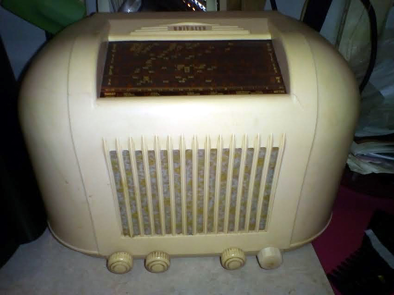 |
|
|
Return to top of page · Post #: 2 · Written at 10:47:15 PM on 28 February 2017.
|
|

|
Location: Hill Top, NSW
Member since 18 September 2015 Member #: 1801 Postcount: 2254 |
|
From what I saw while searching around, there were 27 different valve lineups for that model. |
|
|
Return to top of page · Post #: 3 · Written at 12:27:20 AM on 1 March 2017.
|
|

|
Location: Wangaratta, VIC
Member since 21 February 2009 Member #: 438 Postcount: 5715 |
|
Welcome to your worst nightmare and its not the only one of them that has variations on the variant, which they varied frequently. |
|
|
Return to top of page · Post #: 4 · Written at 7:43:54 AM on 1 March 2017.
|
|

|
Location: Melbourne, VIC
Member since 20 September 2011 Member #: 1009 Postcount: 1263 |
|
I think it could be a 11-20T. |
|
|
Return to top of page · Post #: 5 · Written at 9:27:44 AM on 1 March 2017.
|
|
|
|
Location: Wangaratta, VIC
Member since 21 February 2009 Member #: 438 Postcount: 5715 |
|
What is in a case marked 11-20 does not necessarily represent what is in it. Much of the information (representative of many Australian circuits) is often quite vague in respect of component changes made to compensate for the different parameters of substituted valves. |
|
|
Return to top of page · Post #: 6 · Written at 7:10:58 PM on 1 March 2017.
|
|
|
|
Location: Clare, SA
Member since 27 March 2016 Member #: 1894 Postcount: 513 |
|
That is very interesting, however not only the case but the chassis has 11=20 written on it, the chassis 11-20 plus the valve lineup! It exhibits no roblems as yet, I had it on for several hours last night after re-capping and it sounded great, lots of volume and clarity nd station sensitivity. Short wave works excellent as well. I think I have been very lucky with this one |
|
|
Return to top of page · Post #: 7 · Written at 9:34:59 PM on 1 March 2017.
|
|
|
|
Location: Wangaratta, VIC
Member since 21 February 2009 Member #: 438 Postcount: 5715 |
|
If the set has not been "got at", still has all of the green paint where it should be, and you have an understanding of how a valve radio works, then that gives you a good understanding as to why it won't, if it fails. |
|
|
Return to top of page · Post #: 8 · Written at 11:17:37 PM on 2 March 2017.
|
|

|
Administrator
Location: Naremburn, NSW
Member since 15 November 2005 Member #: 1 Postcount: 7624 |
|
Photo uploaded. ‾‾‾‾‾‾‾‾‾‾‾‾‾‾‾‾‾‾‾‾‾‾‾‾‾‾‾‾‾‾‾‾‾‾‾‾‾‾‾‾‾‾‾‾‾‾‾‾‾‾‾‾‾‾‾‾‾‾‾‾‾‾‾‾‾‾‾‾ A valve a day keeps the transistor away... |
|
|
Return to top of page · Post #: 9 · Written at 9:40:21 PM on 3 March 2017.
|
|
|
|
Location: Clare, SA
Member since 27 March 2016 Member #: 1894 Postcount: 513 |
|
Aha!!! Mine is an 11-20V apparently! |
|
|
« Back ·
1 ·
Next »
|
|
|
You need to be a member to post comments on this forum.
|
|

Sign In
Vintage Radio and Television is proudly brought to you by an era where things were built with pride and made to last.
DISCLAIMER: Valve radios and televisions contain voltages that can deliver lethal shocks. You should not attempt to work on a valve radio or other electrical appliances unless you know exactly what you are doing and have gained some experience with electronics and working around high voltages. The owner, administrators and staff of Vintage Radio & Television will accept no liability for any damage, injury or loss of life that comes as a result of your use or mis-use of information on this website. Please read our Safety Warning before using this website.
WARNING: Under no circumstances should you ever apply power to a vintage radio, television or other electrical appliance you have acquired without first having it checked and serviced by an experienced person. Also, at no time should any appliance be connected to an electricity supply if the power cord is damaged. If in doubt, do not apply power.
Shintara - Keepin' It Real · VileSilencer - Maintain The Rage