
Tech Talk
Forum home - Go back to Tech talk
|
Help in identifying a Chassis make and model
|
|
|
Return to top of page · Post #: 16 · Written at 3:24:37 PM on 15 January 2017.
|
|

|
Location: Wangaratta, VIC
Member since 21 February 2009 Member #: 438 Postcount: 5254 |
|
Picture is worth thousand words - allegedly Confucius. The photos still pixelate however, one of the Ecaps in the other photo shows 25V. |
|
|
Return to top of page · Post #: 17 · Written at 4:11:52 PM on 15 January 2017.
|
|
|
|
Location: Melbourne, VIC
Member since 26 December 2010 Member #: 794 Postcount: 387 |
|
Thanks Mark, I'll email some higher res pics to you shortly, looking at the chassis compared to the M55 circuit there does spear to be some difference - so still at a bit of a loss as to what it is and should look like |
|
|
Return to top of page · Post #: 18 · Written at 4:56:32 PM on 15 January 2017.
|
|
|
|
Location: Wangaratta, VIC
Member since 21 February 2009 Member #: 438 Postcount: 5254 |
|
And what a difference clear photos make. That has been seriously got at. The two caps in the RH top corner are far from original the dark one is English looks like an off the bench one but the voltage rating is right (now is it polyester & not paper?) and the silver one is oil filled. They are as bad as paper & more toxic, it has to go. |
|
|
Return to top of page · Post #: 19 · Written at 9:37:18 PM on 15 January 2017.
|
|
|
|
Location: Wangaratta, VIC
Member since 21 February 2009 Member #: 438 Postcount: 5254 |
|
A couple of thoughts. There is a list of radio models floating about. I have a copy. Tedious but a superb document for looking for sets with a certain valve combination. |
|
|
Return to top of page · Post #: 20 · Written at 10:51:44 PM on 15 January 2017.
|
|
|
|
Location: Melbourne, VIC
Member since 26 December 2010 Member #: 794 Postcount: 387 |
|
Hi Marc, |
|
|
Return to top of page · Post #: 21 · Written at 1:37:53 AM on 16 January 2017.
|
|
|
|
Location: Wangaratta, VIC
Member since 21 February 2009 Member #: 438 Postcount: 5254 |
|
I would note that I was fixing these things before I left school. I really am long past the point of bothering to panic if there is no diagram. With some you are dreaming if you think its going to happen. STC Chassis #59 and an AWA one off being examples. |
|
|
Return to top of page · Post #: 22 · Written at 10:56:34 PM on 16 January 2017.
|
|
|
|
Location: Melbourne, VIC
Member since 26 December 2010 Member #: 794 Postcount: 387 |
|
That makes sense. So I guess then if possible, re wire it to put a 6M5 back as the audio OP tube would be the go. As I'm fairly new to all this, your guidance would be appreciated |
|
|
Return to top of page · Post #: 23 · Written at 10:17:55 AM on 17 January 2017.
|
|
|
|
Location: Wangaratta, VIC
Member since 21 February 2009 Member #: 438 Postcount: 5254 |
|
I am not a fan of modifying until it it is established as to what you have. 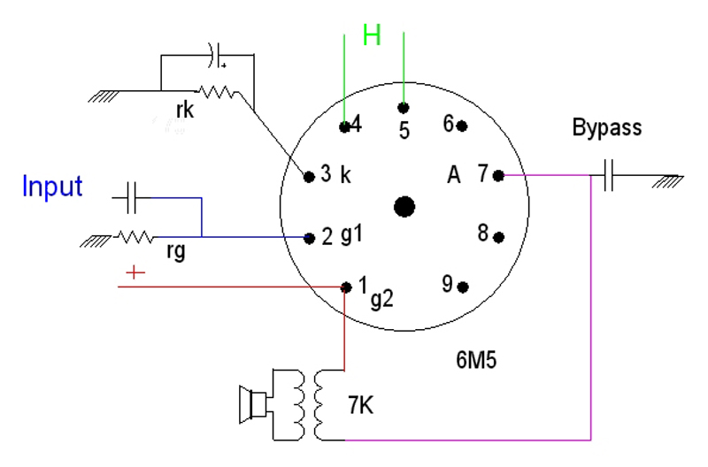 |
|
|
Return to top of page · Post #: 24 · Written at 7:34:21 PM on 17 January 2017.
|
|

|
Administrator
Location: Naremburn, NSW
Member since 15 November 2005 Member #: 1 Postcount: 7301 |
|
Photo uploaded to Post 23. ‾‾‾‾‾‾‾‾‾‾‾‾‾‾‾‾‾‾‾‾‾‾‾‾‾‾‾‾‾‾‾‾‾‾‾‾‾‾‾‾‾‾‾‾‾‾‾‾‾‾‾‾‾‾‾‾‾‾‾‾‾‾‾‾‾‾‾‾ A valve a day keeps the transistor away... |
|
|
Return to top of page · Post #: 25 · Written at 3:25:34 PM on 18 January 2017.
|
|
|
|
Location: Melbourne, VIC
Member since 26 December 2010 Member #: 794 Postcount: 387 |
|
Thanks Marc, |
|
|
Return to top of page · Post #: 26 · Written at 3:31:56 PM on 18 January 2017.
|
|
|
|
Location: Melbourne, VIC
Member since 26 December 2010 Member #: 794 Postcount: 387 |
|
Looking at the speaker connection, 2 pins go to the OP transformer as per above and the other 2 directly to the speaker itself. |
|
|
Return to top of page · Post #: 27 · Written at 5:42:33 PM on 18 January 2017.
|
|

|
Location: Hill Top, NSW
Member since 18 September 2015 Member #: 1801 Postcount: 2014 |
|
I'd still say it is a 6M5. |
|
|
Return to top of page · Post #: 28 · Written at 6:20:11 PM on 18 January 2017.
|
|
|
|
Location: Melbourne, VIC
Member since 26 December 2010 Member #: 794 Postcount: 387 |
|
That's fine and I'm happy to put a 6M5 in, but I'm guessing we would have to modify the current setup to make it work. |
|
|
Return to top of page · Post #: 29 · Written at 10:24:51 PM on 18 January 2017.
|
|
|
|
Location: Wangaratta, VIC
Member since 21 February 2009 Member #: 438 Postcount: 5254 |
|
It looks like our slacker has paralleled the 4μF & 8μF and it was originally a 16μF cap. I thought it had too many. Cathode pin 6M5 grounded says its back biased, like the Presidents mentioned |
|
|
Return to top of page · Post #: 30 · Written at 12:42:11 PM on 19 January 2017.
|
|
|
|
Location: Melbourne, VIC
Member since 26 December 2010 Member #: 794 Postcount: 387 |
|
Hi again, |
|
|
You need to be a member to post comments on this forum.
|
|
Sign In
Vintage Radio and Television is proudly brought to you by an era where things were built with pride and made to last.
DISCLAIMER: Valve radios and televisions contain voltages that can deliver lethal shocks. You should not attempt to work on a valve radio or other electrical appliances unless you know exactly what you are doing and have gained some experience with electronics and working around high voltages. The owner, administrators and staff of Vintage Radio & Television will accept no liability for any damage, injury or loss of life that comes as a result of your use or mis-use of information on this website. Please read our Safety Warning before using this website.
WARNING: Under no circumstances should you ever apply power to a vintage radio, television or other electrical appliance you have acquired without first having it checked and serviced by an experienced person. Also, at no time should any appliance be connected to an electricity supply if the power cord is damaged. If in doubt, do not apply power.
Shintara - Keepin' It Real · VileSilencer - Maintain The Rage