
Tech Talk
Forum home - Go back to Tech talk
|
Philips Radio Model Number?
|
|
|
« Back ·
1 ·
Next »
|
|
|
Return to top of page · Post #: 1 · Written at 9:36:02 AM on 7 December 2016.
|
|
|
|
Location: Tynong North, VIC
Member since 9 April 2009 Member #: 464 Postcount: 37 |
|
Can any one help with a model number for this radio ,valve line up 6N8 ,6AN7 ,6N8 ,6N8 ,6M5. Thanks. 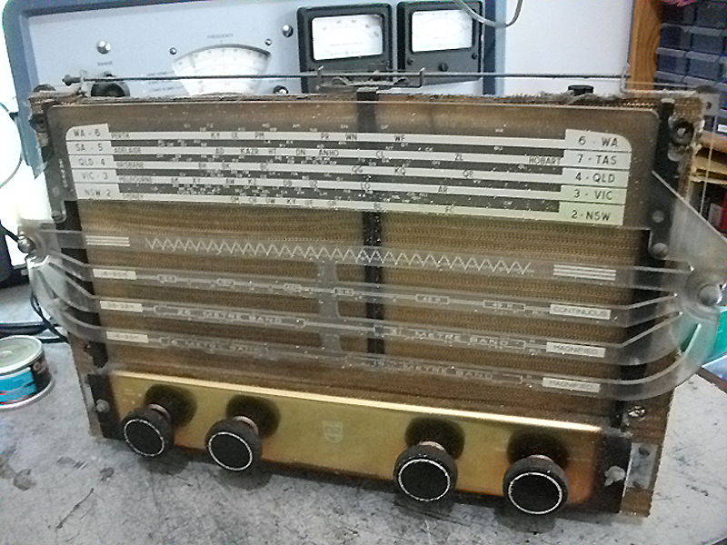 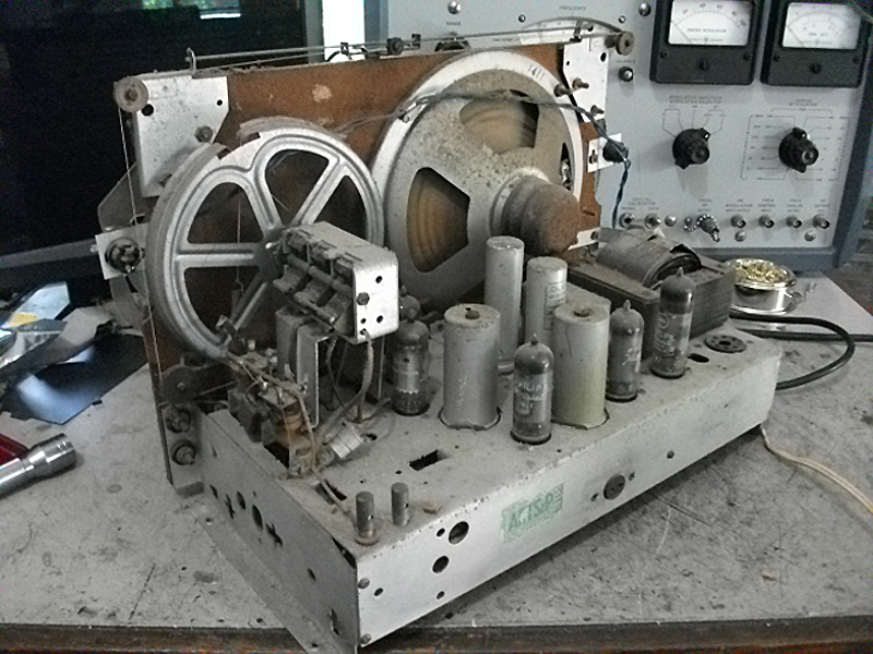 |
|
|
Return to top of page · Post #: 2 · Written at 10:00:14 AM on 7 December 2016.
|
|

|
Location: Beechmont, QLD
Member since 10 April 2009 Member #: 465 Postcount: 109 |
|
Rectifier?, photograph? Not enough information sorry. |
|
|
Return to top of page · Post #: 3 · Written at 9:47:15 PM on 7 December 2016.
|
|

|
Administrator
Location: Naremburn, NSW
Member since 15 November 2005 Member #: 1 Postcount: 7639 |
|
Photos uploaded. ‾‾‾‾‾‾‾‾‾‾‾‾‾‾‾‾‾‾‾‾‾‾‾‾‾‾‾‾‾‾‾‾‾‾‾‾‾‾‾‾‾‾‾‾‾‾‾‾‾‾‾‾‾‾‾‾‾‾‾‾‾‾‾‾‾‾‾‾ A valve a day keeps the transistor away... |
|
|
Return to top of page · Post #: 4 · Written at 12:36:20 AM on 8 December 2016.
|
|

|
Location: Wangaratta, VIC
Member since 21 February 2009 Member #: 438 Postcount: 5730 |
|
Possibly in the era of a 125 around 1951? Would be handy to know valve line up? probably two 6N8, 6AN7, 6M5 and rectifier 6X5. It will be distinguished from 5Y3, by having heaters wired pins 2 & 7, one of which may ground? |
|
|
Return to top of page · Post #: 5 · Written at 12:40:29 AM on 8 December 2016.
|
|

|
Location: Sydney, NSW
Member since 28 January 2011 Member #: 823 Postcount: 6962 |
|
Would be handy to know valve line up? |
|
|
Return to top of page · Post #: 6 · Written at 3:35:21 AM on 8 December 2016.
|
|

|
Location: Melbourne, VIC
Member since 20 September 2011 Member #: 1009 Postcount: 1266 |
|
It is a Model 140 or 140K. |
|
|
Return to top of page · Post #: 7 · Written at 1:34:10 PM on 9 December 2016.
|
|
|
|
Location: Tynong North, VIC
Member since 9 April 2009 Member #: 464 Postcount: 37 |
|
Thank you to all especially Monochrome TV, I downloaded the info. for the 125 (a very nice copy) . The set is in original condition nothing appears to have been changed even the electro's have not been replaced the only exception to this is the 6X5 has been replaced with a diode , I will probably go back to the 6X5 .The radio is physically difficult to work with ,the dial and dial cord mechanism protrude so it can't be turned upside down or stood on its end ,I will have to construct a stand to be able to work with it. Thanks again. |
|
|
Return to top of page · Post #: 8 · Written at 11:15:53 PM on 9 December 2016.
|
|
|
|
Location: Wangaratta, VIC
Member since 21 February 2009 Member #: 438 Postcount: 5730 |
|
A couple of bits of wood screwed onto the sides (holes are there) and braced to stop them spreading, works wonders. No hammering with valves in. |
|
|
« Back ·
1 ·
Next »
|
|
|
You need to be a member to post comments on this forum.
|
|
Sign In
Vintage Radio and Television is proudly brought to you by an era where things were built with pride and made to last.
DISCLAIMER: Valve radios and televisions contain voltages that can deliver lethal shocks. You should not attempt to work on a valve radio or other electrical appliances unless you know exactly what you are doing and have gained some experience with electronics and working around high voltages. The owner, administrators and staff of Vintage Radio & Television will accept no liability for any damage, injury or loss of life that comes as a result of your use or mis-use of information on this website. Please read our Safety Warning before using this website.
WARNING: Under no circumstances should you ever apply power to a vintage radio, television or other electrical appliance you have acquired without first having it checked and serviced by an experienced person. Also, at no time should any appliance be connected to an electricity supply if the power cord is damaged. If in doubt, do not apply power.
Shintara - Keepin' It Real · VileSilencer - Maintain The Rage