
Tech Talk
Forum home - Go back to Tech talk
|
Using an op-amp 'rectifier' as an AM detector
|
|
|
« Back ·
1 ·
Next »
|
|
|
Return to top of page · Post #: 1 · Written at 3:47:35 PM on 4 December 2016.
|
|
|
|
Location: Oradell, US
Member since 2 April 2010 Member #: 643 Postcount: 839 |
|
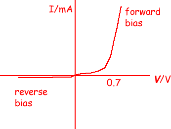
Using a high speed op-amp, in this case a HA2525, I built a "rectifier" circuit as an AM detector. Idea is that it should be more linear than an ordinary diode. The HA2525 has a slew rate of 120v/uS, and enough bandwidth to do unity gain to around 10MHz or more. You can find the datasheet here. |
|
|
Return to top of page · Post #: 2 · Written at 7:09:26 PM on 4 December 2016.
|
|
|
|
Location: Belrose, NSW
Member since 31 December 2015 Member #: 1844 Postcount: 2712 |
|
Maybe you should try a standard op-amp peak detector circuit. It's self-biassing - no pots needed. 1 op-amp, 1 diode, 1 cap., 1 resistor. |
|
|
Return to top of page · Post #: 3 · Written at 10:13:58 AM on 5 December 2016.
|
|
|
|
Location: Melbourne, VIC
Member since 5 October 2009 Member #: 555 Postcount: 470 |
|
Good stuff, guys ..... interesting ....and challenging .... ‾‾‾‾‾‾‾‾‾‾‾‾‾‾‾‾‾‾‾‾‾‾‾‾‾‾‾‾‾‾‾‾‾‾‾‾‾‾‾‾‾‾‾‾‾‾‾‾‾‾‾‾‾‾‾‾‾‾‾‾‾‾‾‾‾‾‾‾ Cheers, Ian |
|
|
Return to top of page · Post #: 4 · Written at 1:22:01 PM on 5 December 2016.
|
|
|
|
Location: Belrose, NSW
Member since 31 December 2015 Member #: 1844 Postcount: 2712 |
|
Actually, this thread got me wondering...... |
|
|
« Back ·
1 ·
Next »
|
|
|
You need to be a member to post comments on this forum.
|
|


Sign In
Vintage Radio and Television is proudly brought to you by an era where things were built with pride and made to last.
DISCLAIMER: Valve radios and televisions contain voltages that can deliver lethal shocks. You should not attempt to work on a valve radio or other electrical appliances unless you know exactly what you are doing and have gained some experience with electronics and working around high voltages. The owner, administrators and staff of Vintage Radio & Television will accept no liability for any damage, injury or loss of life that comes as a result of your use or mis-use of information on this website. Please read our Safety Warning before using this website.
WARNING: Under no circumstances should you ever apply power to a vintage radio, television or other electrical appliance you have acquired without first having it checked and serviced by an experienced person. Also, at no time should any appliance be connected to an electricity supply if the power cord is damaged. If in doubt, do not apply power.
Shintara - Keepin' It Real · VileSilencer - Maintain The Rage