
Tech Talk
Forum home - Go back to Tech talk
|
80 2A5 58 57 ?
|
|
|
« Back ·
1 ·
Next »
|
|
|
Return to top of page · Post #: 1 · Written at 2:47:04 PM on 24 October 2016.
|
|
|
|
Location: Melbourne, VIC
Member since 25 January 2015 Member #: 1686 Postcount: 30 |
|
Hi , have up loaded some photos, Thanks Brad,.What I have here is radio from 30s, no name or numbers ,with the line up 80 2a5 58 57 and unknown ? Pic Of Valve. 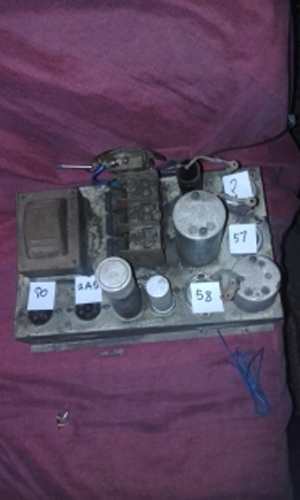 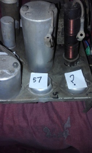 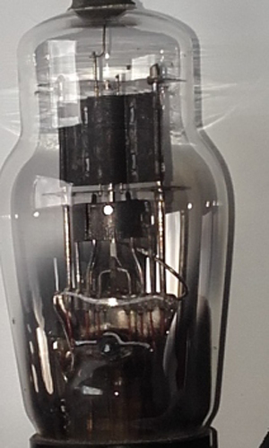 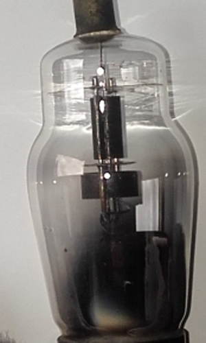 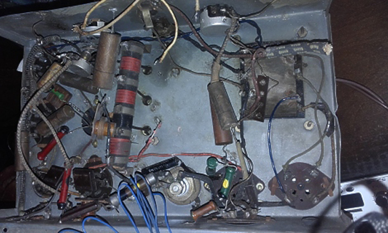 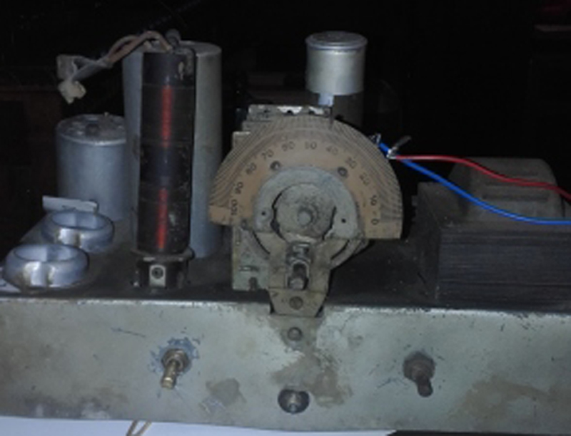 |
|
|
Return to top of page · Post #: 2 · Written at 3:49:14 PM on 24 October 2016.
|
|

|
Location: Wangaratta, VIC
Member since 21 February 2009 Member #: 438 Postcount: 5733 |
|
I will await photos. I have repaired a procession of radios with that combination and different brands. its probably missing another #58. |
|
|
Return to top of page · Post #: 3 · Written at 6:44:55 PM on 2 November 2016.
|
|
|
|
Location: Melbourne, VIC
Member since 25 January 2015 Member #: 1686 Postcount: 30 |
|
Another Question ?, if anyone has any ideas,On the 4th photo is a input connection,between the sound and tone pots that is just a bit smaller than a modern earphone plug, when looked from underneath it is wired directly to the mains wire.This I suppose was some kind of On / Off..:..Dangerious I would think ! Was it a common thing from radios from the 30s? Its not a later addition, But when looking at the whole unit it seems to be home built, even though it is very old. A few German and English components,Made be a mail order unit or something? This ones not for me. Just Curious I Guess |
|
|
Return to top of page · Post #: 4 · Written at 8:49:08 PM on 2 November 2016.
|
|

|
Location: Sydney, NSW
Member since 28 January 2011 Member #: 823 Postcount: 6965 |
|
I suppose was some kind of On / Off..:..Dangerous I would think ! Was it a common thing from radios from the 30s? |
|
|
Return to top of page · Post #: 5 · Written at 9:51:19 PM on 2 November 2016.
|
|
|
|
Location: Wangaratta, VIC
Member since 21 February 2009 Member #: 438 Postcount: 5733 |
|
Looks like the dog's dinner. What sort of camera was used? Fuzzy photo's are not helpful. Auto focus can be a problem. The tripod is not obsolete. You can improve depth of field by moving back & by using a higher number f stop then cropping it later. |
|
|
Return to top of page · Post #: 6 · Written at 10:15:06 PM on 2 November 2016.
|
|

|
Location: Hill Top, NSW
Member since 18 September 2015 Member #: 1801 Postcount: 2264 |
|
although it appears to resemble an RCA phono jack |
|
|
Return to top of page · Post #: 7 · Written at 10:41:06 PM on 2 November 2016.
|
|
|
|
Location: Sydney, NSW
Member since 28 January 2011 Member #: 823 Postcount: 6965 |
|
looks very like a headphone jack. |
|
|
Return to top of page · Post #: 8 · Written at 12:28:52 AM on 3 November 2016.
|
|
|
|
Location: Wangaratta, VIC
Member since 21 February 2009 Member #: 438 Postcount: 5733 |
|
I believe the mains cord is not related to that jack. There may (?) be a resistor to replace the choke and hopefully a set of high impedance headphones were used on the 2A5 which would see them in the plate circuit. |
|
|
Return to top of page · Post #: 9 · Written at 3:08:23 PM on 4 November 2016.
|
|
|
|
Location: Melbourne, VIC
Member since 25 January 2015 Member #: 1686 Postcount: 30 |
|
Yes Thanks, All that info, on board, Like I said it is in a bad way electrically, and mainly brought for cabinet Which has a mini amp playing usb 3mp fm aux input with a couple of good speakers sounds better that it ever could or would have. The power cord Had a plug on it when I brought it...and it just goes to show what dangers are out there. luckily, for the past couple of years getting heaps of info from this forum,I understand And just cut the power cord on any vintage radio untill ive had a good look at everything. Unfortunately ive reached my Max of photos, but it defiantly has a input, just a bit smaller than a modern mini ear phone socket. And this is connected directly to one side of the power cord. the other side of the power cord is connected to the transformer.? |
|
|
Return to top of page · Post #: 10 · Written at 4:58:22 PM on 4 November 2016.
|
|
|
|
Location: Belrose, NSW
Member since 31 December 2015 Member #: 1844 Postcount: 2715 |
|
I have seen a phone jack used as push-pull switch or momentary switch. Maybe for tone control, not power. |
|
|
Return to top of page · Post #: 11 · Written at 9:58:42 AM on 5 November 2016.
|
|
|
|
Location: Wangaratta, VIC
Member since 21 February 2009 Member #: 438 Postcount: 5733 |
|
I am not backing away from this being hacked & the dog's dinner would be tidier. That Phono plug does not belong there, the volume pot likely does. With the distance traveled there is likely a need for at minimum an added tag strip and shielded wire. |
|
|
« Back ·
1 ·
Next »
|
|
|
You need to be a member to post comments on this forum.
|
|
Sign In
Vintage Radio and Television is proudly brought to you by an era where things were built with pride and made to last.
DISCLAIMER: Valve radios and televisions contain voltages that can deliver lethal shocks. You should not attempt to work on a valve radio or other electrical appliances unless you know exactly what you are doing and have gained some experience with electronics and working around high voltages. The owner, administrators and staff of Vintage Radio & Television will accept no liability for any damage, injury or loss of life that comes as a result of your use or mis-use of information on this website. Please read our Safety Warning before using this website.
WARNING: Under no circumstances should you ever apply power to a vintage radio, television or other electrical appliance you have acquired without first having it checked and serviced by an experienced person. Also, at no time should any appliance be connected to an electricity supply if the power cord is damaged. If in doubt, do not apply power.
Shintara - Keepin' It Real · VileSilencer - Maintain The Rage