
Tech Talk
Forum home - Go back to Tech talk
|
Circuit diagram wanted for HMV Nippergram C13D from 1952 (Opinions too!)
|
|
|
Return to top of page · Post #: 1 · Written at 1:24:18 PM on 10 September 2016.
|
|
|
|
Location: Clare, SA
Member since 27 March 2016 Member #: 1894 Postcount: 513 |
|
Hello, I bought this gem recently on ebay for a mere $75, and it is immaculate, surprised it didn't start a bidding frenzy! Well I got lucky there... Gorgeous little tablegram with 78 turntable. it was advertised as "Caps" replaced, and worked well as soon as I plugged it in, except for a loud "mains hum" which I straight away thought a little ominous, however dismissed it as maybe just normal for this model perhaps as with a little volume, it was drowned out. We (wife and I) enjoyed some Jelly Roll records for a bit then left the radio playing, when suddenly my wife exclaimed "what happened to the radio?" I popped up an ear to notice it had got very quiet and scratchy sounding, upon investigation I noticed another station was trying to muscle in on the one we were enjoying, but no matter how I tried to tune it I could get the station I wanted, but not the previous volume and clarity and even the record player suffered loss of volume and there was a "hot antiquey electronic" smell coming from it when I leaned closer and sniffed, not unpleasant just there, and noticeable a little more than I'd consider normal. I turned it off and the following day I noticed no improvement in sound quality and the mains hum too loud for my liking, so powered off and opened her up to find indeed all new caps with the exception of one large, particularly nasty looking electrolytic, which I snipped out immediately. It is rated 24+24 mfd with two wires coming out or the + side, but only one was connected! Hmmn thew plot thickens. I'm now wondering why it was left and why only one of the two wires was connected, and if the other was supposed to go somewhere? Before I simply replace it with a goody, if I can get a circuit, I'd like to peruse such to see if I can gander where that other wire may be meant to go as it seems illogical and a tad odd that such a capacitor would be put there if only half of it was to be used? 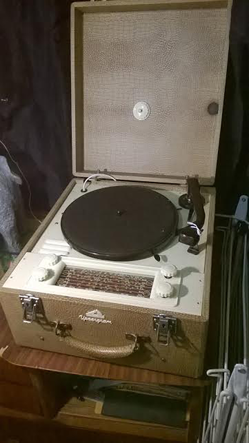  |
|
|
Return to top of page · Post #: 2 · Written at 3:30:59 PM on 10 September 2016.
|
|

|
Location: Sydney, NSW
Member since 28 January 2011 Member #: 823 Postcount: 6956 |
|
It is rated 24+24 mfd with two wires coming out or the + side, but only one was connected! Hmmn the plot thickens. I'm now wondering why it was left and why only one of the two wires was connected, and if the other was supposed to go somewhere? |
|
|
Return to top of page · Post #: 3 · Written at 4:31:15 PM on 10 September 2016.
|
|
|
|
Location: Clare, SA
Member since 27 March 2016 Member #: 1894 Postcount: 513 |
|
Thanks GTC, as I suspected! It would be illogical to have a 2 function cap if not needed! Thank you for your help! It was probably the output transformer overheating creating the hot smell with the faulty cap starving the circuit of power. |
|
|
Return to top of page · Post #: 4 · Written at 4:34:45 PM on 10 September 2016.
|
|
|
|
Location: Clare, SA
Member since 27 March 2016 Member #: 1894 Postcount: 513 |
|
Just a quick one, now I have more caps in my arsenal, would you recommend using 22μF to replace a 24μF, or putting 16μF and 8μF parallel to create 24μF? That would be more accurate, just wondering if 22μF would suffice or the more accurate option being better? |
|
|
Return to top of page · Post #: 5 · Written at 4:47:11 PM on 10 September 2016.
|
|
|
|
Location: Sydney, NSW
Member since 28 January 2011 Member #: 823 Postcount: 6956 |
|
22μF should suffice as long as the working voltage is high enough. Such electros do hard work and need to be able to handle high ripple current. |
|
|
Return to top of page · Post #: 6 · Written at 6:52:40 PM on 10 September 2016.
|
|
|
|
Location: Clare, SA
Member since 27 March 2016 Member #: 1894 Postcount: 513 |
|
Oh dear, new electro's soldered in, turned on and no mains hum whatsoever, but to my dismay the volume is less than a third of what it should be and sounds like a fuzz box, not a pleasure to listen to, so obviously it is damaged somehow, I'm hoping it's the 6m5 output valve as I have two newies on their way from Thailand, which I bought for my Astorm if it's not a valve I shudder to think what could have gone wrong with it, it sounded so loud and clear the other night and we were really happy with it... Now it's a radio fuzz box. I'm hoping it's not the power transformer, but if there's sound, it must still be ok one would hope? |
|
|
Return to top of page · Post #: 7 · Written at 7:03:32 PM on 10 September 2016.
|
|
|
|
Location: Clare, SA
Member since 27 March 2016 Member #: 1894 Postcount: 513 |
|
Just guessing, but the rectifier tube would bear the brunt of carnage from a shorting filter cap most likely? Looking at the circuit it seems to be the component most in harms way after the transformer? |
|
|
Return to top of page · Post #: 8 · Written at 7:10:00 PM on 10 September 2016.
|
|
|
|
Location: Sydney, NSW
Member since 28 January 2011 Member #: 823 Postcount: 6956 |
|
What's the DC voltage on the cathode (pin 7) of the 6X4? |
|
|
Return to top of page · Post #: 9 · Written at 8:13:12 PM on 10 September 2016.
|
|
|
|
Location: Clare, SA
Member since 27 March 2016 Member #: 1894 Postcount: 513 |
|
Yes DC voltage measured carefully showing 267 volts, there are two big resistors in parallel, the other side of which is where the electrolytic cap (bad one) was connected to ground, I'm getting 170 volts there. Pin 7 is where the other 24μF positive of the cap was supposed to connect to, but nothing was there, it had been left disconnected, but has now been fixed. I have a 500V 22μF now going to pin 7 and a 450v 22μF going to the other side of the resistor where the bad cap was connected. |
|
|
Return to top of page · Post #: 10 · Written at 9:05:44 PM on 10 September 2016.
|
|
|
|
Location: Sydney, NSW
Member since 28 January 2011 Member #: 823 Postcount: 6956 |
|
Rectifier and transformer seem okay then. |
|
|
Return to top of page · Post #: 11 · Written at 9:06:59 PM on 10 September 2016.
|
|
|
|
Location: Clare, SA
Member since 27 March 2016 Member #: 1894 Postcount: 513 |
|
Tracing the circuit, It seems the output transformer could be overloaded via the grid of the 6m5 if C18 was to short and I'm a bit worried as measuring the output transformer in the 20k range on my multimeter, I'm getting .59 which suggests an internal short or crook multimeter? Athough it gives a pop when I crack a 9v battery across it? Not sure there. |
|
|
Return to top of page · Post #: 12 · Written at 9:16:33 PM on 10 September 2016.
|
|

|
Location: Hill Top, NSW
Member since 18 September 2015 Member #: 1801 Postcount: 2256 |
|
Can you post a link to the schematic? I cannot offer assistance without it. |
|
|
Return to top of page · Post #: 13 · Written at 9:25:28 PM on 10 September 2016.
|
|
|
|
Location: Clare, SA
Member since 27 March 2016 Member #: 1894 Postcount: 513 |
|
I think my new acquisition is going to be consigned to the sick bay with my Astor until I can get a couple of output transformers, some cheeky stinker pipped me to the post on the ones I bid on via ebay in the last hour, so it seems I can only source them from Canada, unless I try modding line transformers, which seems a bit tricky, so maybe best just ordering two from Canada and awaiting their arrival.... I'll know next time, regardless of what claims are made, re-capping etc. just pull the bloody thing to bits and have a good sticky beak, before plugging in assuming all is well, I think it's like I find with cars as a mechanic, it's not what people tell you they've done, it's what they selectively don't tell you! Like they get too embarrassed to mention something they've cocked up... Leaving you up to your neck chasing a wild goose, when owning up would save a repairer a world of trouble. My fault really... I should never have taken anything for granted once I heard that hum. The lack of hum, now those electro's are replaced illustrates that. Silly me. |
|
|
Return to top of page · Post #: 14 · Written at 9:27:45 PM on 10 September 2016.
|
|
|
|
Location: Sydney, NSW
Member since 28 January 2011 Member #: 823 Postcount: 6956 |
|
Let's not indict the O/P transformer just yet. |
|
|
Return to top of page · Post #: 15 · Written at 9:31:59 PM on 10 September 2016.
|
|
|
|
Location: Clare, SA
Member since 27 March 2016 Member #: 1894 Postcount: 513 |
|
No Robbbert sorry, GTC emailed it to me, but I don't have yours, if you email me a "test" email, I can send you the pdf. But I have come to the same conclusion as GTC that the output tranny is the likely culprit, apparently HMV's are prone to internal shorts and my multimeter is supporting that conclusion... Alas. |
|
|
You need to be a member to post comments on this forum.
|
|
Sign In
Vintage Radio and Television is proudly brought to you by an era where things were built with pride and made to last.
DISCLAIMER: Valve radios and televisions contain voltages that can deliver lethal shocks. You should not attempt to work on a valve radio or other electrical appliances unless you know exactly what you are doing and have gained some experience with electronics and working around high voltages. The owner, administrators and staff of Vintage Radio & Television will accept no liability for any damage, injury or loss of life that comes as a result of your use or mis-use of information on this website. Please read our Safety Warning before using this website.
WARNING: Under no circumstances should you ever apply power to a vintage radio, television or other electrical appliance you have acquired without first having it checked and serviced by an experienced person. Also, at no time should any appliance be connected to an electricity supply if the power cord is damaged. If in doubt, do not apply power.
Shintara - Keepin' It Real · VileSilencer - Maintain The Rage