
Tech Talk
Forum home - Go back to Tech talk
|
HMV Little Nipper Super Five
|
|
|
« Back ·
1 ·
Next »
|
|
|
Return to top of page · Post #: 1 · Written at 8:32:49 PM on 30 June 2016.
|
|

|
Location: Latham, ACT
Member since 21 February 2015 Member #: 1705 Postcount: 2247 |
|
I have started work on this little baby and am quite surprised at the quality of the components in it. 90% of the caps are the Philips ceramic types of which I am told hardly ever give any grief. I changed the power cord and two ducon electros plus two Ducon .0100μF caps. It does work and is very sensitive but very low volume and slightly distorted. My next trick is to test all the resistors . What I found very strange was there was two 10k resistors wound together to make a 5k resistor and this was actually illustrated in the service manual "why would this be so". why not just have a larger 5k resistor. Also can any of you tell me in plain English how to test the high tension voltage and heater voltage ie where to put the probe that's not on the valve. I am using this little baby to help myself to learn these basics and if all else fails I will take it to my buddy that lives around the corner. I will be gifting this one to my brother inlaw in the Philippines at Christmas time. 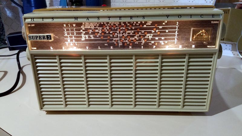 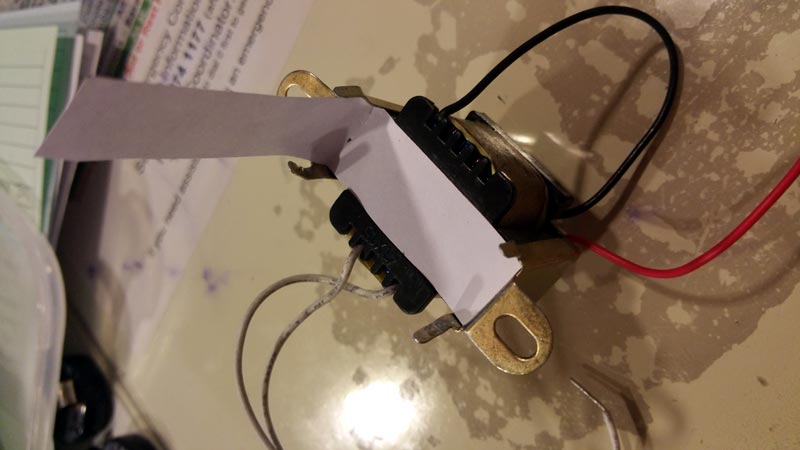 |
|
|
Return to top of page · Post #: 2 · Written at 9:00:36 PM on 30 June 2016.
|
|

|
Location: Hill Top, NSW
Member since 18 September 2015 Member #: 1801 Postcount: 2264 |
|
I'm assuming the two 10k resistors are in the filter circuit, between the 2 main filter electros. |
|
|
Return to top of page · Post #: 3 · Written at 9:05:14 PM on 30 June 2016.
|
|
|
|
Location: Latham, ACT
Member since 21 February 2015 Member #: 1705 Postcount: 2247 |
|
That's exactly where they are. |
|
|
Return to top of page · Post #: 4 · Written at 10:38:49 PM on 30 June 2016.
|
|

|
Location: Wangaratta, VIC
Member since 21 February 2009 Member #: 438 Postcount: 5733 |
|
I tend to behave as a commercial fixer as I often do that. There is far less risk of damage & considerable stress to be avoided, when the set fails to fire up, if you check the resistors & replace them as you change the caps. |
|
|
Return to top of page · Post #: 5 · Written at 1:06:18 AM on 1 July 2016.
|
|
|
|
Location: Latham, ACT
Member since 21 February 2015 Member #: 1705 Postcount: 2247 |
|
Ok so its sounds like I am on the right track checking the resistors then. |
|
|
Return to top of page · Post #: 6 · Written at 1:11:30 AM on 1 July 2016.
|
|
|
|
Location: Latham, ACT
Member since 21 February 2015 Member #: 1705 Postcount: 2247 |
|
My Main question is this. Knowing where to put the probe on the valve where do I put the other probe to check the voltage is it the chassis or somewhere else. Ie to check the HT and heater voltage. |
|
|
Return to top of page · Post #: 7 · Written at 8:40:16 AM on 1 July 2016.
|
|
|
|
Location: Latham, ACT
Member since 21 February 2015 Member #: 1705 Postcount: 2247 |
|
I did get to replace the 10 meg resistor this morning and there has been noticeable improvement. I will endeavour to test all resistors especially the high value ones. |
|
|
Return to top of page · Post #: 8 · Written at 9:39:33 AM on 1 July 2016.
|
|
|
|
Location: Wangaratta, VIC
Member since 21 February 2009 Member #: 438 Postcount: 5733 |
|
In finding just one dud resistor, you reinforce my comment. Rework is undesirable, time wasting, and presents additional risk. The general rule of thumb, bearing in mind that some resistors cannot be accurately tested "in circuit", is that if it is high in circuit it is more than probable that it is a dud. |
|
|
Return to top of page · Post #: 9 · Written at 6:13:24 PM on 1 July 2016.
|
|
|
|
Location: Latham, ACT
Member since 21 February 2015 Member #: 1705 Postcount: 2247 |
|
As a rule I never test resistors in circuit. On Monday night I will seek out all the high value resistors and change them out. Then we may be looking to test the valves. |
|
|
Return to top of page · Post #: 10 · Written at 11:41:50 PM on 1 July 2016.
|
|
|
|
Location: Wangaratta, VIC
Member since 21 February 2009 Member #: 438 Postcount: 5733 |
|
You can test quite a few in circuit, but you need to understand it relative to where it is and the device you use. A common LV ohm meter be it digital, or analogue, has insufficient voltage to be able to see a cold valve as anything other than an open circuit. |
|
|
Return to top of page · Post #: 11 · Written at 3:16:11 AM on 26 July 2016.
|
|
|
|
Location: Latham, ACT
Member since 21 February 2015 Member #: 1705 Postcount: 2247 |
|
Well I found what the problem was with this little baby. Its speaker transformer was open circuit. What threw me was that there was still sound but low volume . Well I bought a speaker transformer from Jaycar and converted it to operate on valve radio and hey presto I have a very strong little performer. I could always remember this one as a child was a very strong performer and its back to its former glory. |
|
|
Return to top of page · Post #: 12 · Written at 12:54:40 PM on 26 July 2016.
|
|

|
Location: Sydney, NSW
Member since 28 January 2011 Member #: 823 Postcount: 6965 |
|
A re-cap of that model here (he doesn't attend to performance issues): https://www.youtube.com/watch?v=Zv0eSZSXp-k |
|
|
Return to top of page · Post #: 13 · Written at 10:04:42 PM on 26 July 2016.
|
|

|
Administrator
Location: Naremburn, NSW
Member since 15 November 2005 Member #: 1 Postcount: 7643 |
|
Photos uploaded. ‾‾‾‾‾‾‾‾‾‾‾‾‾‾‾‾‾‾‾‾‾‾‾‾‾‾‾‾‾‾‾‾‾‾‾‾‾‾‾‾‾‾‾‾‾‾‾‾‾‾‾‾‾‾‾‾‾‾‾‾‾‾‾‾‾‾‾‾ A valve a day keeps the transistor away... |
|
|
Return to top of page · Post #: 14 · Written at 12:56:13 AM on 28 July 2016.
|
|
|
|
Location: Latham, ACT
Member since 21 February 2015 Member #: 1705 Postcount: 2247 |
|
Managed to find time to watch the above youtube clip and when it showed the two electros it confirmed in my mind that one of the originals in mine was actually reversed. I would be asking how this happened because they were the original caps. how did this radio ever work unless it was reversed later by someone that had no idea. |
|
|
Return to top of page · Post #: 15 · Written at 1:37:30 AM on 28 July 2016.
|
|
|
|
Location: Sydney, NSW
Member since 28 January 2011 Member #: 823 Postcount: 6965 |
|
how did this radio ever work unless it was reversed later by someone that had no idea. |
|
|
« Back ·
1 ·
Next »
|
|
|
You need to be a member to post comments on this forum.
|
|
Sign In
Vintage Radio and Television is proudly brought to you by an era where things were built with pride and made to last.
DISCLAIMER: Valve radios and televisions contain voltages that can deliver lethal shocks. You should not attempt to work on a valve radio or other electrical appliances unless you know exactly what you are doing and have gained some experience with electronics and working around high voltages. The owner, administrators and staff of Vintage Radio & Television will accept no liability for any damage, injury or loss of life that comes as a result of your use or mis-use of information on this website. Please read our Safety Warning before using this website.
WARNING: Under no circumstances should you ever apply power to a vintage radio, television or other electrical appliance you have acquired without first having it checked and serviced by an experienced person. Also, at no time should any appliance be connected to an electricity supply if the power cord is damaged. If in doubt, do not apply power.
Shintara - Keepin' It Real · VileSilencer - Maintain The Rage