Welcome to Australia's only Vintage Radio and Television discussion forums. You are not logged in. Please log in below, apply for an account or retrieve your password.
Australian Vintage Radio Forums
  Home  ·  About Us  ·  Discussion Forums  ·  Glossary  ·  Outside Links  ·  Policies  ·  Services Directory  ·  Safety Warnings  ·  Tutorials

Tech Talk

Forum home - Go back to Tech talk

 Auditec 300W Amp model 2084
« Back · 1 · Next »
 Return to top of page · Post #: 1 · Written at 11:18:21 AM on 13 June 2016.
Kakadumh's Gravatar
 Location: Darlington, WA
 Member since 30 March 2016
 Member #: 1897
 Postcount: 183

Not quite "vintage" but getting that way...I have the above type amp given to me ages ago as no longer working.

Not surprised when I found that the fuse holder was broken in half & I foolishly thought this would be an easy fix!! Once powered up some rather nasty hissing sounds coming from one of the 10,000 μF 65V filter caps had me switching it off real quick.

4 NEW filter caps later even though most of the old ones had checked OK all looked good but absolutely NO sound on either channel.

Auditec have long since ceased making amps & circuits it seems are rather a rarity so hopefully someone here just MIGHT have or know of where I can get hold of the circuit.

Any clues anyone??

Lindsay

If a photo helps can do but these were a very common amp used in many cinemas across Australia but with the digital conversions many were simply thrown in the bin as the old gear was torn out.


 Return to top of page · Post #: 2 · Written at 5:38:44 PM on 13 June 2016.
Marcc's avatar
 Location: Wangaratta, VIC
 Member since 21 February 2009
 Member #: 438
 Postcount: 5252

A photo just might indicate if it can be reverse engineered. I have had to do that a few times.

Marc


 Return to top of page · Post #: 3 · Written at 8:19:42 PM on 13 June 2016.
Kakadumh's Gravatar
 Location: Darlington, WA
 Member since 30 March 2016
 Member #: 1897
 Postcount: 183

Have sent Brad a photo to upload if it helps in anyway possible.

So far have identified that the small cct board on the rear panel between the input & output sockets is the "Dethump" board to protect the speakers at switch on.

The 2 channels are the larger boards either side attached to the hefty heatsinks & the output is 4 x MJI5024 transistors in each. Yet to pull one of those boards out to check what semis are fitted on those boards.

In the front centre between the 2 VU meters is the "Overload" sense board as the 2 Red lamps on the front panel are wired into that board.

Power supply is derived from the toroidal trannie in the centre producing 2 x 60V DC rails one Pos & one Neg.

I have a smaller brother to this beast and the output boards are nothing like this unit...the smaller one is only 100W per channel this is 300W per channel.

I am trying to track down a cinema equipment installer friend who just might have a copy of these amps but so far he is unable to be contacted.

Lindsay

Auditech Amplifier


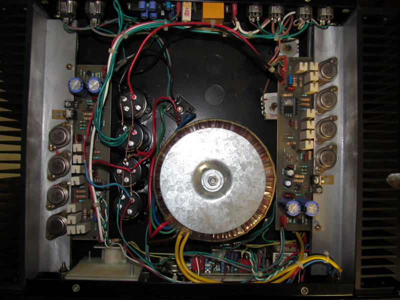
 Return to top of page · Post #: 4 · Written at 11:57:12 PM on 13 June 2016.
Viccadillac's Gravatar
 Location: Perth, WA
 Member since 7 May 2012
 Member #: 1140
 Postcount: 157

Hi Lindsay,

Very similar to a Altronics redback pa amp I parted out a couple of years back . I have a HSE pro amp that also is very similar in design.

Very simple in design and shouldn't take too long to pin point any problems . Good luck.

Cheers
Vic


 Return to top of page · Post #: 5 · Written at 12:17:00 AM on 14 June 2016.
GTC's avatar
 GTC
 Location: Sydney, NSW
 Member since 28 January 2011
 Member #: 823
 Postcount: 6686

Auditec have long since ceased making amps & circuits it seems are rather a rarity so hopefully someone here just MIGHT have or know of where I can get hold of the circuit

This is the current entry in the white pages. Have you been in contact with them?

"Auditec Australia Pty Ltd, a company based in Mount Kuring-Gai in the Australian state of New South Wales. Their main business area is audio Amplifiers."

Director
Joe Beskin

Auditec Australia Pty Ltd
16 King St
Mount Kuring-Gai 2080
New South Wales

Postal Address:
P O Box 88
Mount Kuring-Gai 2080
New South Wales

Phone: 61 2 9457 6000
Fax: 61 2 9457 6006


 Return to top of page · Post #: 6 · Written at 9:42:55 AM on 14 June 2016.
Marcc's avatar
 Location: Wangaratta, VIC
 Member since 21 February 2009
 Member #: 438
 Postcount: 5252

You may be able to bluff your way to the issue. To me assuming both amp boards are dead has to be proven and the common link discounted.

The common link is the power supply. During the 90's there were a whole lot of caps made to a stolen planted formula. That cost $millions as they failed, just in computer boards. I just recently realised that there were two candidates in a "No-break" built 1992: Both had failed; Is this from that era?

At this point I would be concentrating on the PSU those big caps would have a fairly hefty inrush current and one feral that had lost polarity from a long sit between charges, may have been the last straw.

As has been suggested that could be a badge engineered job & an arrangement made between the designer & the manufacturer. Badge engineering is far from new.

Marc


 Return to top of page · Post #: 7 · Written at 12:03:47 PM on 14 June 2016.
Kakadumh's Gravatar
 Location: Darlington, WA
 Member since 30 March 2016
 Member #: 1897
 Postcount: 183

GTC,

The Auditec contact was my first port of call & the gentleman that answered the phone informed me that Auditec that made the amps had ceased to operate & they had NO information whatsoever regarding any amplifiers made. I thought I was onto a hot lead when I called only to be disappointed in the end.

Marc,

All 4 of those PS caps are brand new and give out the 60V + & - rails OK.

Vic,

I think this amp predates the Redback stuff & possibly goes back to mid 70's given the history of the cinema it came out of.

Looks like naught else to do but sit down with a good light & some blank paper & start making some sense out of the PCB tracks & what is dangled off them.
Slow & tedious work.

Thanks for all comments,

Lindsay


 Return to top of page · Post #: 8 · Written at 5:20:41 PM on 14 June 2016.
Marcc's avatar
 Location: Wangaratta, VIC
 Member since 21 February 2009
 Member #: 438
 Postcount: 5252

You may have missed my point re the caps. You pointed out that one of the originals had failed.

Whilst the modern ones are better, Electrolytics have in earlier times been a constant problem and in old sets & still are. These things are chemical and rely on a coating of oxide to act as an insulator. Left unused for long periods of time, that oxide layer, which is maintained by a leakage current, is lost.

When powered without a proper startup procedure called "re-forming" (Which, with many we don't bother with due to age & type.). This restores (reforms) the oxide layer. Failure to do this often sees them present as a short circuit and often explode.

With transistorised stuff they used them as coupling capacitors. In car radios and some other things (No break, TV......) they dry out (a second issue). Apart from poor filtering in power supplies, them drying out results in loss of volume in amplifiers etc where they are the coupling cap.

The duds of the nineties tended to ooze out electrolyte.

Marc


 Return to top of page · Post #: 9 · Written at 7:07:09 PM on 14 June 2016.
Kakadumh's Gravatar
 Location: Darlington, WA
 Member since 30 March 2016
 Member #: 1897
 Postcount: 183

Marcc,

Still not quite seeing what you are getting at re caps...the only other caps are to 2 smaller ones on each amp board...will check them before I start trying to nut out the circuit.

I did not bother trying to reform them prior to instal as the only reform functions I have available is the 250V & 25V functions on an old Palec valve tester.

In common with most of these large torodial fitted amps is that there is a hefty whump from that area at switch on & the 3 big Ampower 200/200W brutes at my past cinema did exactly that same noise each night as we powered the bio box up.
This Auditec makes much the same noise & unlike some with dodgy caps there is no tripping of 240V circuit breakers at switch on and then immediately after it is fine.

Lindsay


 Return to top of page · Post #: 10 · Written at 8:03:05 PM on 14 June 2016.
Marcc's avatar
 Location: Wangaratta, VIC
 Member since 21 February 2009
 Member #: 438
 Postcount: 5252

There are actually to my eyes four electrolytics on each board. Those two larger Blue things look like something around a 1000μF Cap.

Between them & the other four that can be a fairly hefty inrush current and that can blow fuses. The other is basically a warning re electrolytic caps left sitting as they can and have done a lot of damage when their condition & characteristics have been ignored.

The other thing is the type of fuse. On a lot of switch mode power supplies powering monitors and such, which have high inrush current, they use a slow blow fuse. It is normally very close to the actual on load current but has a high instantaneous thermal inertia, allowing it to run about 5-10 seconds over current before blowing.

I often use my VCT on LV caps that have been sitting a while in storage as long as they are over 25V. I have a home built reformer on the bench PSU that can get to 400V. VCT is around 225VDC according to its paperwork. VCT should have a couple of wax paper caps in it.
Replace them if you have not already.

Marc


 Return to top of page · Post #: 11 · Written at 12:08:29 PM on 15 June 2016.
Kakadumh's Gravatar
 Location: Darlington, WA
 Member since 30 March 2016
 Member #: 1897
 Postcount: 183

Marc,

Yep, missed those 2 little black caps on each board but found them yesterday when I dragged both boards out , lifted the caps & checked them all (8) to be OK.
Looking to find a suitable replacement for all 8 & about to wander down the hill to Jaycar & see what they can offer....replacing them just in case. Nought else on the board looks suss.

On the VCT I was taught to use the 500V Meg Ohm range to reform any caps higher than 250V. Seemed to do the job OK.

There was NO fuse in this amp when I got it as the fuseholder was busted but the front panel has it labelled as 5A & as the other amps at the past cinema all used Slow Blow that's what I whacked in this one as the toroidal transformers seem to have a savage inrush at switch on.

Lindsay


 Return to top of page · Post #: 12 · Written at 1:41:12 PM on 20 June 2016.
Kakadumh's Gravatar
 Location: Darlington, WA
 Member since 30 March 2016
 Member #: 1897
 Postcount: 183

The more I prod around this thing the more puzzled I become. Reverse Engineering is proving a challenge.

The output stage uses 4 x MJ15024 transistors. 2 each in parallel and the Emitters of one pair feed the speaker circuit via a 0.15 ohm resistor & the other pair feed that same point from their Collectors in parallel also via a 0.15 ohm resistor.

I would have expected to see a pair of NPN transistors hooked up by their Emitters to the Speaker lead & the Emitters of a pair of PNP transistors hooked to the same point (Complimentary/Symmetry configuration) such as a pair of MJ15024 & MJ15025. The Collectors going off to the respective Pos & Neg power supplies with the other side of the speaker line being the "0" Volt point

What on earth is that sort of output stage config??? anyone got any ideas??

The smaller Auditec amp I have .100W per side uses the Complimentary/Symmetry config with just a pair of MJ15024/MJ15025 & I have sourced a circuit for that but nothing like this 300W beast

Lindsay


« Back · 1 · Next »
 You need to be a member to post comments on this forum.

Sign In

Username:
Password:
 Keep me logged in.
Do not tick box on a computer with public access.