
Tech Talk
Forum home - Go back to Tech talk
|
Schematic needed AWA EFCO usl 46
|
|
|
Return to top of page · Post #: 1 · Written at 8:22:58 AM on 9 May 2016.
|
|
|
|
Location: Brisbane, QLD
Member since 9 May 2016 Member #: 1921 Postcount: 5 |
|
Hello 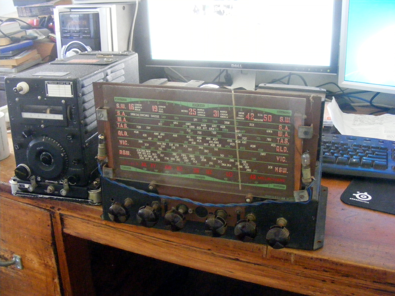 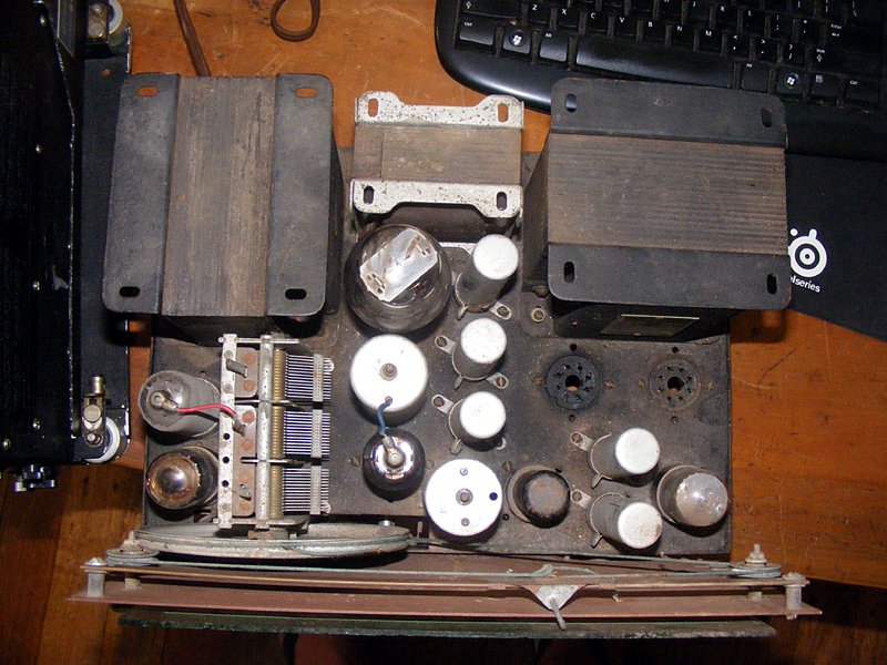 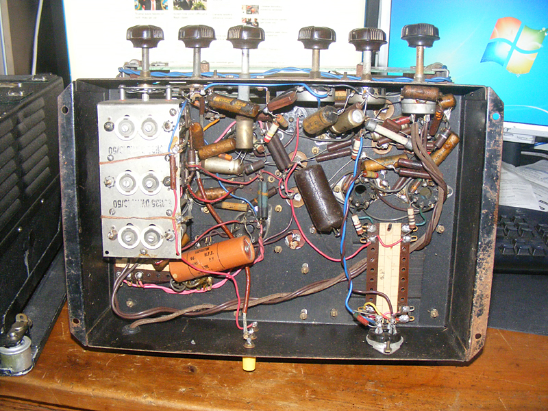 |
|
|
Return to top of page · Post #: 2 · Written at 10:41:27 AM on 9 May 2016.
|
|

|
Location: Hill Top, NSW
Member since 18 September 2015 Member #: 1801 Postcount: 2253 |
|
Can you link to photos on ebay, or post some of your own? |
|
|
Return to top of page · Post #: 3 · Written at 3:14:19 PM on 9 May 2016.
|
|

|
Location: Wangaratta, VIC
Member since 21 February 2009 Member #: 438 Postcount: 5709 |
|
Something sounds odd EFCO made dials. AWA is possibly a dial they used? I cannot see AWA using the Philps valve even during the war. HMV 661 used EBF2G with a circuit mod during the war when the tubes ran out: That was superseded by EBF35 / EBF32; KT 61(Tetrode) is also not a common OP valve. |
|
|
Return to top of page · Post #: 4 · Written at 6:04:56 PM on 9 May 2016.
|
|

|
Administrator
Location: Naremburn, NSW
Member since 15 November 2005 Member #: 1 Postcount: 7622 |
|
Photos uploaded. ‾‾‾‾‾‾‾‾‾‾‾‾‾‾‾‾‾‾‾‾‾‾‾‾‾‾‾‾‾‾‾‾‾‾‾‾‾‾‾‾‾‾‾‾‾‾‾‾‾‾‾‾‾‾‾‾‾‾‾‾‾‾‾‾‾‾‾‾ A valve a day keeps the transistor away... |
|
|
Return to top of page · Post #: 5 · Written at 1:07:39 AM on 10 May 2016.
|
|

|
Location: Sydney, NSW
Member since 28 January 2011 Member #: 823 Postcount: 6948 |
|
I can't find anything with that particular valve line-up in the usual places. Maybe they are not the original/correct valves. |
|
|
Return to top of page · Post #: 6 · Written at 7:19:55 AM on 10 May 2016.
|
|
|
|
Location: Brisbane, QLD
Member since 9 May 2016 Member #: 1921 Postcount: 5 |
|
Hello |
|
|
Return to top of page · Post #: 7 · Written at 8:08:10 AM on 10 May 2016.
|
|
|
|
Location: Sydney, NSW
Member since 28 January 2011 Member #: 823 Postcount: 6948 |
|
There is kind of a printed tag on the back with what looks like "ARTS&P" |
|
|
Return to top of page · Post #: 8 · Written at 8:12:21 AM on 10 May 2016.
|
|
|
|
Location: Brisbane, QLD
Member since 9 May 2016 Member #: 1921 Postcount: 5 |
|
The tag is light blue/light green...more blue, and the ARTS&P is printed in a darker blue. |
|
|
Return to top of page · Post #: 9 · Written at 10:06:12 AM on 10 May 2016.
|
|
|
|
Location: Wangaratta, VIC
Member since 21 February 2009 Member #: 438 Postcount: 5709 |
|
The grey tube is likely the pentagrid and the set clearly has an RF stage ahead of it. Definitely looks like some hefty PP tubes like 6L6 in the OP. Big remaining tube looks like a filament rectifier like 5Y3 or heftier. |
|
|
Return to top of page · Post #: 10 · Written at 11:27:02 AM on 11 May 2016.
|
|
|
|
Location: Hill Top, NSW
Member since 18 September 2015 Member #: 1801 Postcount: 2253 |
|
Let's presume for the moment that the valves are the correct ones. |
|
|
Return to top of page · Post #: 11 · Written at 1:19:16 PM on 11 May 2016.
|
|
|
|
Location: Brisbane, QLD
Member since 9 May 2016 Member #: 1921 Postcount: 5 |
|
Hello |
|
|
Return to top of page · Post #: 12 · Written at 3:41:23 PM on 11 May 2016.
|
|
|
|
Location: Hill Top, NSW
Member since 18 September 2015 Member #: 1801 Postcount: 2253 |
|
6SN7GT (2 triodes), sounds correct, one triode is a preamp, other half is the phase inverter. |
|
|
Return to top of page · Post #: 13 · Written at 5:43:19 PM on 11 May 2016.
|
|
|
|
Location: Brisbane, QLD
Member since 9 May 2016 Member #: 1921 Postcount: 5 |
|
Thanks for your advice. |
|
|
Return to top of page · Post #: 14 · Written at 6:55:12 PM on 11 May 2016.
|
|
|
|
Location: Hill Top, NSW
Member since 18 September 2015 Member #: 1801 Postcount: 2253 |
|
Throw ALL the old caps out, not just the ones that show leakage on your meter. The gooey stuff is wax. Even if they measure good, they WILL leak when hot, and even a 30megohm leak can upset valve operating conditions by allowing high voltages to get to the grid circuits. (Yes, valves are that sensitive). |
|
|
Return to top of page · Post #: 15 · Written at 12:56:50 AM on 12 May 2016.
|
|
|
|
Location: Wangaratta, VIC
Member since 21 February 2009 Member #: 438 Postcount: 5709 |
|
I did post on this seems to have gone awry? I have sent Brad a pic of a circuit consistent with what I am thinking. |
|
|
You need to be a member to post comments on this forum.
|
|
 2 and 8 ohms output and a trimax choke.
Sign In
Vintage Radio and Television is proudly brought to you by an era where things were built with pride and made to last.
DISCLAIMER: Valve radios and televisions contain voltages that can deliver lethal shocks. You should not attempt to work on a valve radio or other electrical appliances unless you know exactly what you are doing and have gained some experience with electronics and working around high voltages. The owner, administrators and staff of Vintage Radio & Television will accept no liability for any damage, injury or loss of life that comes as a result of your use or mis-use of information on this website. Please read our Safety Warning before using this website.
WARNING: Under no circumstances should you ever apply power to a vintage radio, television or other electrical appliance you have acquired without first having it checked and serviced by an experienced person. Also, at no time should any appliance be connected to an electricity supply if the power cord is damaged. If in doubt, do not apply power.
Shintara - Keepin' It Real · VileSilencer - Maintain The Rage