
Tech Talk
Forum home - Go back to Tech talk
|
Video Amplifier Question
|
|
|
« Back ·
1 ·
Next »
|
|
|
Return to top of page · Post #: 1 · Written at 4:23:04 PM on 19 March 2016.
|
|
|
Location: Silver City WI, US
Member since 10 May 2013 Member #: 1340 Postcount: 977 |
|
I am unsure of the reason they connect a 2μF capacitor from cathode to screen on this early RCA TV 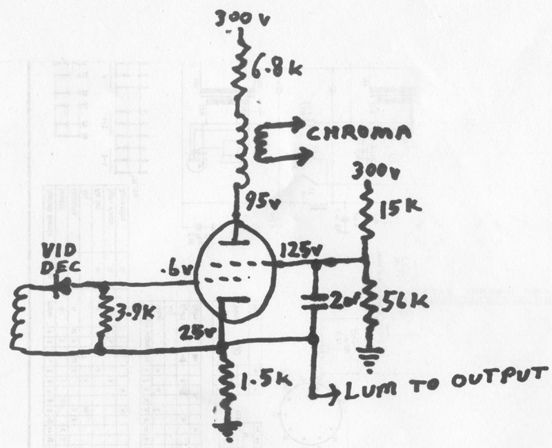 |
|
|
Return to top of page · Post #: 2 · Written at 10:13:21 AM on 24 March 2016.
|
|

|
Location: Beechmont, QLD
Member since 10 April 2009 Member #: 465 Postcount: 109 |
|
That is so the valve acts as a pentode, by fixing the screen, as far as the signal is concerned, to the cathode potential. This valve is used as both a common cathode amplifier, for the chrominance signal, and a cathode follower, for the luminance signal. |
|
|
Return to top of page · Post #: 3 · Written at 2:33:01 PM on 24 March 2016.
|
|
|
|
Location: Silver City WI, US
Member since 10 May 2013 Member #: 1340 Postcount: 977 |
|
Why not just use the 2μF capacitor to decouple the screen (to ground)? Would it not work just as well? |
|
|
Return to top of page · Post #: 4 · Written at 12:29:01 PM on 4 April 2016.
|
|
|
|
Location: Silver City WI, US
Member since 10 May 2013 Member #: 1340 Postcount: 977 |
|
One way to observe the effect of signal connection from cathode to screen would be to remove detector diode and feed the amplifier a Multiburst test signal: then monitor the output at the plate of the 2nd video stage (serving as a buffer stage for this purpose). Then jump out the chroma trap for "flat" response. Then note any difference in gain or response when the 2μF is removed, or grounded. Although Multiburst test signal generators are hard to come by (only used for testing broadcast systems). |
|
|
« Back ·
1 ·
Next »
|
|
|
You need to be a member to post comments on this forum.
|
|
Sign In
Vintage Radio and Television is proudly brought to you by an era where things were built with pride and made to last.
DISCLAIMER: Valve radios and televisions contain voltages that can deliver lethal shocks. You should not attempt to work on a valve radio or other electrical appliances unless you know exactly what you are doing and have gained some experience with electronics and working around high voltages. The owner, administrators and staff of Vintage Radio & Television will accept no liability for any damage, injury or loss of life that comes as a result of your use or mis-use of information on this website. Please read our Safety Warning before using this website.
WARNING: Under no circumstances should you ever apply power to a vintage radio, television or other electrical appliance you have acquired without first having it checked and serviced by an experienced person. Also, at no time should any appliance be connected to an electricity supply if the power cord is damaged. If in doubt, do not apply power.
Shintara - Keepin' It Real · VileSilencer - Maintain The Rage