
Tech Talk
Forum home - Go back to Tech talk
|
AWA 608T
|
|
|
« Back ·
1 ·
Next »
|
|
|
Return to top of page · Post #: 1 · Written at 5:35:31 PM on 7 March 2016.
|
|

|
Location: Latham, ACT
Member since 21 February 2015 Member #: 1705 Postcount: 2236 |
|
Hey, guys, I have managed to take a look at this old girl today. It is the first vibrator unit I have experienced. I recall Marcc giving a little advice on these a few days back about a 1KV cap. Is this cap usually in the vibrator or is it the one in the underside of the chassis. Comments welcome please. 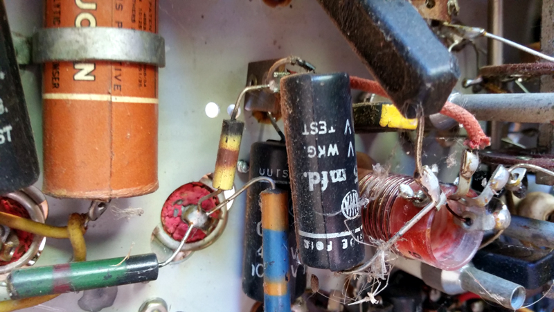 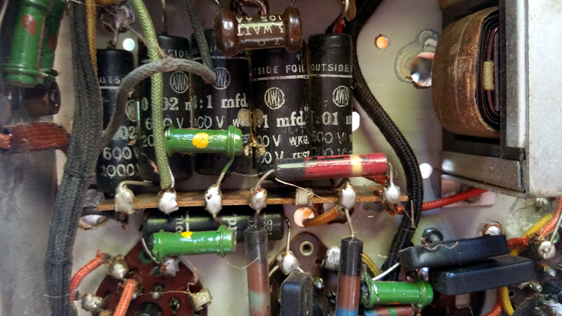 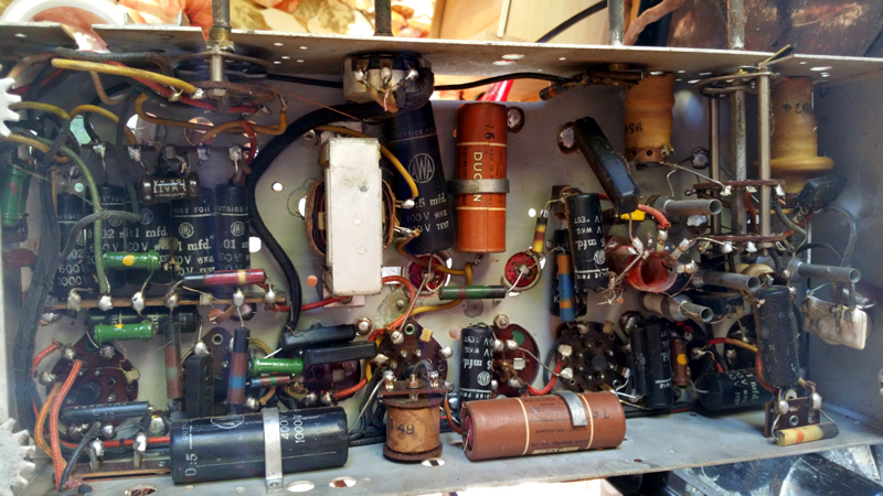 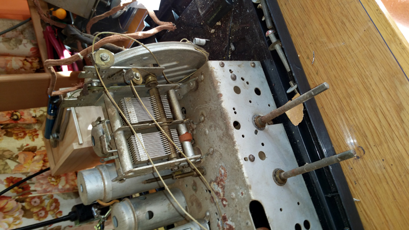 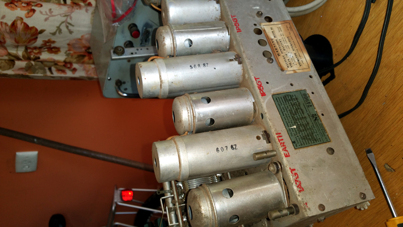 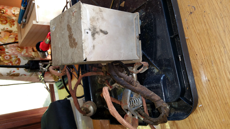 |
|
|
Return to top of page · Post #: 2 · Written at 11:48:32 PM on 7 March 2016.
|
|

|
Location: Wangaratta, VIC
Member since 21 February 2009 Member #: 438 Postcount: 5720 |
|
The set seems to use a lot of 600V caps with a test voltage in the order of 2KVV. This looks like most of the c70's are these and inside the vibrator unit. It is shown as a separate item in AORSM's. |
|
|
Return to top of page · Post #: 3 · Written at 11:05:44 PM on 11 March 2016.
|
|
|
|
Location: Latham, ACT
Member since 21 February 2015 Member #: 1705 Postcount: 2236 |
|
Yes the Vibrator is seperate. Just seeing these caps with high test voltages started me thinking. I will do the vibrator up first as it looks in good shape but the wiring harness will be replaced. |
|
|
Return to top of page · Post #: 4 · Written at 11:31:33 PM on 11 March 2016.
|
|
|
|
Location: Wangaratta, VIC
Member since 21 February 2009 Member #: 438 Postcount: 5720 |
|
One thing to watch with the vibrator units themselves. A lot had foam inside & out to dampen the noise. This was a Formaldehyde based foam and turns to dust. If it has done that inside the can then it invariably stops it from working and it has to be cleaned out. |
|
|
Return to top of page · Post #: 5 · Written at 8:09:17 AM on 18 April 2016.
|
|
|
|
Location: Latham, ACT
Member since 21 February 2015 Member #: 1705 Postcount: 2236 |
|
Well guys this has all been successfully done. Out of the 5 valves would you believe that 3 were shot, one being the output valve and another being the oscillator. I have managed to be able to secure NOS spares of all of them so its not so bad. |
|
|
« Back ·
1 ·
Next »
|
|
|
You need to be a member to post comments on this forum.
|
|
Sign In
Vintage Radio and Television is proudly brought to you by an era where things were built with pride and made to last.
DISCLAIMER: Valve radios and televisions contain voltages that can deliver lethal shocks. You should not attempt to work on a valve radio or other electrical appliances unless you know exactly what you are doing and have gained some experience with electronics and working around high voltages. The owner, administrators and staff of Vintage Radio & Television will accept no liability for any damage, injury or loss of life that comes as a result of your use or mis-use of information on this website. Please read our Safety Warning before using this website.
WARNING: Under no circumstances should you ever apply power to a vintage radio, television or other electrical appliance you have acquired without first having it checked and serviced by an experienced person. Also, at no time should any appliance be connected to an electricity supply if the power cord is damaged. If in doubt, do not apply power.
Shintara - Keepin' It Real · VileSilencer - Maintain The Rage