
Tech Talk
Forum home - Go back to Tech talk
|
STC Valve Radio
|
|
|
Return to top of page · Post #: 1 · Written at 5:33:00 PM on 16 January 2016.
|
|
|
|
Location: Warrnambool, VIC
Member since 16 January 2016 Member #: 1858 Postcount: 19 |
|
Hello everyone I have recently purchased this STC valve radio and the electrical side of it is in rather good condition, however my concern with the set is, what voltage is it meant to be running, instinct tells me it should be 240v however when I purchased the radio the lead had two crocodile clips on it? this has made me second guess my self. 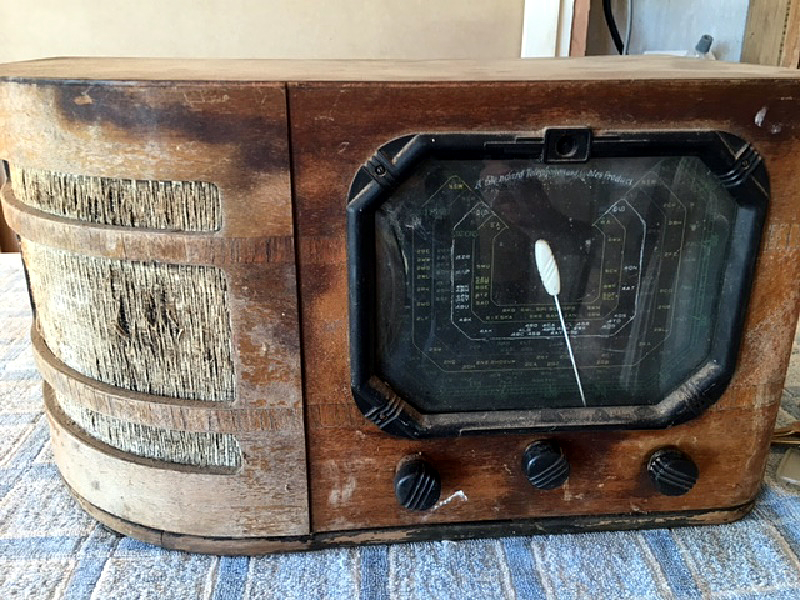 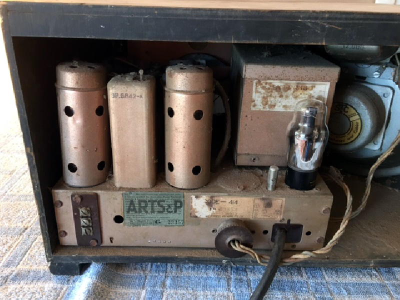 |
|
|
Return to top of page · Post #: 2 · Written at 6:00:23 PM on 16 January 2016.
|
|

|
Location: Hill Top, NSW
Member since 18 September 2015 Member #: 1801 Postcount: 2254 |
|
Photos would be a good idea, plus if you could give us the valve types, that would make things a lot easier. |
|
|
Return to top of page · Post #: 3 · Written at 6:05:22 PM on 16 January 2016.
|
|
|
|
Location: Warrnambool, VIC
Member since 16 January 2016 Member #: 1858 Postcount: 19 |
|
Hey there, I have emailed the photos to the admin as per instructions ? is there another way to post them ? |
|
|
Return to top of page · Post #: 4 · Written at 6:54:32 PM on 16 January 2016.
|
|
|
|
Location: Hill Top, NSW
Member since 18 September 2015 Member #: 1801 Postcount: 2254 |
|
The 1-volt valves make me think it's a battery model. |
|
|
Return to top of page · Post #: 5 · Written at 6:58:13 PM on 16 January 2016.
|
|
|
|
Location: Warrnambool, VIC
Member since 16 January 2016 Member #: 1858 Postcount: 19 |
|
That's what I thought ! would we be talking 32 volts or 12 volts ? |
|
|
Return to top of page · Post #: 6 · Written at 7:14:31 PM on 16 January 2016.
|
|
|
|
Location: Hill Top, NSW
Member since 18 September 2015 Member #: 1801 Postcount: 2254 |
|
Not sure yet, let's wait for one of the others to link a schematic, or may have knowledge of that model. |
|
|
Return to top of page · Post #: 7 · Written at 7:22:33 PM on 16 January 2016.
|
|

|
Administrator
Location: Naremburn, NSW
Member since 15 November 2005 Member #: 1 Postcount: 7624 |
|
Images are usually posted by 22:00 NSW time on the day they are e-mailed. Often it is slightly earlier but if I am out of town it can be up to 48 hours. I'll be home tonight so they should be up before the deadline. ‾‾‾‾‾‾‾‾‾‾‾‾‾‾‾‾‾‾‾‾‾‾‾‾‾‾‾‾‾‾‾‾‾‾‾‾‾‾‾‾‾‾‾‾‾‾‾‾‾‾‾‾‾‾‾‾‾‾‾‾‾‾‾‾‾‾‾‾ A valve a day keeps the transistor away... |
|
|
Return to top of page · Post #: 8 · Written at 7:26:01 PM on 16 January 2016.
|
|
|
|
Location: Warrnambool, VIC
Member since 16 January 2016 Member #: 1858 Postcount: 19 |
|
Hey Brad thank you for the info |
|
|
Return to top of page · Post #: 9 · Written at 8:36:26 PM on 16 January 2016.
|
|

|
Location: Wangaratta, VIC
Member since 21 February 2009 Member #: 438 Postcount: 5715 |
|
Are we sure about 414? Most of those like 415 were 6V That voltage should be on the vibrator if its not missing? |
|
|
Return to top of page · Post #: 10 · Written at 9:33:49 PM on 16 January 2016.
|
|
|
|
Location: Warrnambool, VIC
Member since 16 January 2016 Member #: 1858 Postcount: 19 |
|
Hello , the vibrator is present and rated at 6 volts, however given the presents of a transformer I wasn't sure. |
|
|
Return to top of page · Post #: 11 · Written at 10:53:11 PM on 16 January 2016.
|
|
|
|
Location: Wangaratta, VIC
Member since 21 February 2009 Member #: 438 Postcount: 5715 |
|
The transformer is likely centre tapped on both sides and is actually part of the vibrator circuit. |
|
|
Return to top of page · Post #: 12 · Written at 12:57:00 AM on 17 January 2016.
|
|
|
|
Location: Warrnambool, VIC
Member since 16 January 2016 Member #: 1858 Postcount: 19 |
|
Just ran the set on six volts the vibrator runs and the 1f7 1d5 and 1f7 heat however the |
|
|
Return to top of page · Post #: 13 · Written at 1:18:06 AM on 17 January 2016.
|
|
|
|
Location: Hill Top, NSW
Member since 18 September 2015 Member #: 1801 Postcount: 2254 |
|
Sounds promising. |
|
|
Return to top of page · Post #: 14 · Written at 7:21:04 AM on 17 January 2016.
|
|

|
Location: Melbourne, VIC
Member since 20 September 2011 Member #: 1009 Postcount: 1263 |
|
Kevin Chant has the STC 414 R & S schematic: |
|
|
Return to top of page · Post #: 15 · Written at 10:36:42 AM on 17 January 2016.
|
|
|
|
Location: Warrnambool, VIC
Member since 16 January 2016 Member #: 1858 Postcount: 19 |
|
Thanks guys this information is of great help are there any further tips on where to start looking for |
|
|
You need to be a member to post comments on this forum.
|
|

Sign In
Vintage Radio and Television is proudly brought to you by an era where things were built with pride and made to last.
DISCLAIMER: Valve radios and televisions contain voltages that can deliver lethal shocks. You should not attempt to work on a valve radio or other electrical appliances unless you know exactly what you are doing and have gained some experience with electronics and working around high voltages. The owner, administrators and staff of Vintage Radio & Television will accept no liability for any damage, injury or loss of life that comes as a result of your use or mis-use of information on this website. Please read our Safety Warning before using this website.
WARNING: Under no circumstances should you ever apply power to a vintage radio, television or other electrical appliance you have acquired without first having it checked and serviced by an experienced person. Also, at no time should any appliance be connected to an electricity supply if the power cord is damaged. If in doubt, do not apply power.
Shintara - Keepin' It Real · VileSilencer - Maintain The Rage