
Tech Talk
Forum home - Go back to Tech talk
|
Hotpoint Version of the 573 MA
|
|
|
Return to top of page · Post #: 1 · Written at 2:11:30 AM on 16 January 2016.
|
|

|
Location: Latham, ACT
Member since 21 February 2015 Member #: 1705 Postcount: 2228 |
|
http://www.kevinchant.com/uploads/7/1/0/8/7108231/573-ma.pdf |
|
|
Return to top of page · Post #: 2 · Written at 2:38:59 AM on 16 January 2016.
|
|

|
Location: Hill Top, NSW
Member since 18 September 2015 Member #: 1801 Postcount: 2253 |
|
I assume you are talking about C25, close to the transformer? It connects between the rectifier (6X4) cathode, and the back-bias supply (provides the grid bias to V4 output valve), positive end to the cathode. The back-bias end has a small 470K resistor connected to it. A measurement should show 150 ohms to earth (the value of R17). |
|
|
Return to top of page · Post #: 3 · Written at 2:47:44 AM on 16 January 2016.
|
|
|
|
Location: Latham, ACT
Member since 21 February 2015 Member #: 1705 Postcount: 2228 |
|
Yes thats correct. I am just wondering if it's got two capacitors or what because I am not going to replace the can. I just wish to put the new caps underneath. |
|
|
Return to top of page · Post #: 4 · Written at 2:50:21 AM on 16 January 2016.
|
|
|
|
Location: Hill Top, NSW
Member since 18 September 2015 Member #: 1801 Postcount: 2253 |
|
It should be a single capacitor, according to both the manual and my experience with those radios, unless someone has done something.... |
|
|
Return to top of page · Post #: 5 · Written at 2:52:33 AM on 16 January 2016.
|
|
|
|
Location: Latham, ACT
Member since 21 February 2015 Member #: 1705 Postcount: 2228 |
|
I have sent some pics but I will take a real close up for a better look. 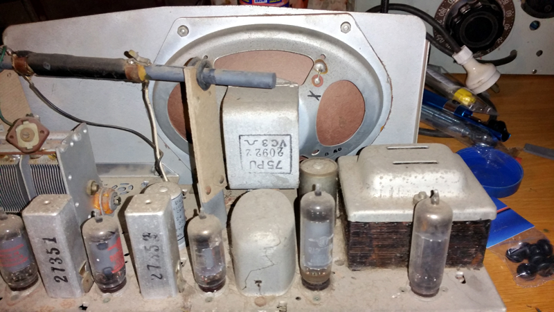 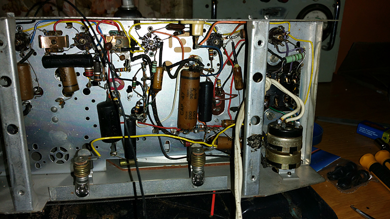 |
|
|
Return to top of page · Post #: 6 · Written at 3:03:46 PM on 17 January 2016.
|
|
|
|
Location: Belrose, NSW
Member since 31 December 2015 Member #: 1844 Postcount: 2710 |
|
Because of the back bias, that cap is isolated from the chassis. There are two twist-lugs that attach it to the insulator - then 100 ohms or 150 ohms to ground. |
|
|
Return to top of page · Post #: 7 · Written at 4:16:44 PM on 17 January 2016.
|
|

|
Location: Wangaratta, VIC
Member since 21 February 2009 Member #: 438 Postcount: 5715 |
|
Bearing in mind that I often fix commercially. There are a few things I would not do to that set. |
|
|
Return to top of page · Post #: 8 · Written at 6:39:36 PM on 17 January 2016.
|
|
|
|
Location: Latham, ACT
Member since 21 February 2015 Member #: 1705 Postcount: 2228 |
|
Ok guys this has set me on the correct path. I am grateful for your input. I have a few nights off this week so I might get stuck into it. And I can Assure you I never leave those old power cables in situ, it is cut and I leave it there till everything else is done and then I put the new cable on. 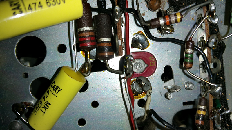 |
|
|
Return to top of page · Post #: 9 · Written at 12:36:30 AM on 19 January 2016.
|
|
|
|
Location: Latham, ACT
Member since 21 February 2015 Member #: 1705 Postcount: 2228 |
|
Now what I have done to replace this cap (CAN) is to cut the resistor and the red wires away . I joined the red wires and the yellow cap ( which is out of this picture ) together. then I rerouted the resistor to the far end of the red wire (on the valve socket) then connected the positive end of the new 22μF electro and the negative end to where the old cap is earthed. I do believe that this is ok. any thoughts?. . I will send new pics. Oh and dont panic I will be replacing the power cable before I power it up. It's just that Jaycar are not open at 00.30 am which is quite thoughtless of them lol.   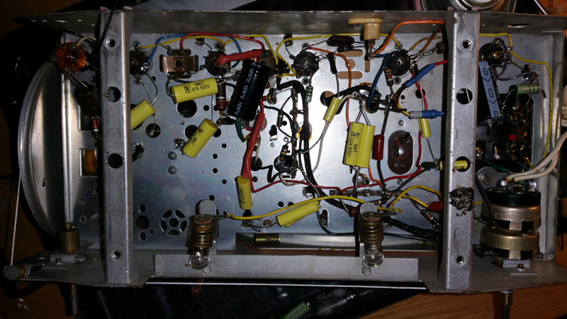 |
|
|
Return to top of page · Post #: 10 · Written at 11:58:15 AM on 19 January 2016.
|
|
|
|
Location: Wangaratta, VIC
Member since 21 February 2009 Member #: 438 Postcount: 5715 |
|
Now there are cheap cables out there & more than one source. I hope one lot have mended their ways since I had a face to face with one of there sales team & pointed out that cost is one thing & quality is another & like the recall of all that house electrical wire. Might be why that mob is in trouble. Reducing the expensive plasticiser that makes it flexible will have ramifications. |
|
|
Return to top of page · Post #: 11 · Written at 7:37:50 PM on 19 January 2016.
|
|
|
|
Location: Latham, ACT
Member since 21 February 2015 Member #: 1705 Postcount: 2228 |
|
Powered it up successfully. Got noise. Lots of interference. Then just noise. Set about and replaced all of the resistors near the valves. (some were definetly not factory). Still have intermittent interference and distortion which goes to nothing. Started tapping the valves with no response untill I tapped the IF CANS. Yep they made heaps of noise so I'm guessing I may have to do surgery on them. Looks like I will replace all the micas any way or could be some dry joints. Thoughts please. 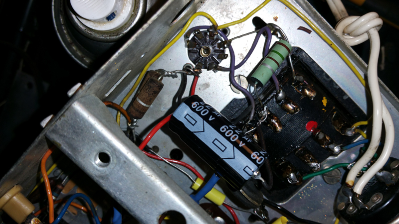 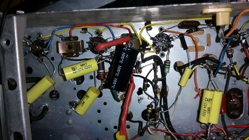  |
|
|
Return to top of page · Post #: 12 · Written at 6:21:56 PM on 23 January 2016.
|
|
|
|
Location: Latham, ACT
Member since 21 February 2015 Member #: 1705 Postcount: 2228 |
|
Right guys this baby had a meltdown a few days back ie stuffed rectifier valve and possibly transformer as well . But I am thinking because the chassis is so neat and clean I am going to do a total rebuild . ie wire for wire and component for comnponent. once I test the tranny I will work ou if I need to rewind it ( which will be done ) or or not but I am not going to give up with out a fight lol. |
|
|
Return to top of page · Post #: 13 · Written at 9:15:32 PM on 23 January 2016.
|
|
|
|
Location: Hill Top, NSW
Member since 18 September 2015 Member #: 1801 Postcount: 2253 |
|
That's sad, sounds like you shorted out the rectified HT. |
|
|
Return to top of page · Post #: 14 · Written at 12:18:25 AM on 24 January 2016.
|
|
|
|
Location: Wangaratta, VIC
Member since 21 February 2009 Member #: 438 Postcount: 5715 |
|
Check also pins 1 &7 of the 6AQ5 both of those pins are grid 1 and its not unusual for some hacker to use one as a tag strip. |
|
|
Return to top of page · Post #: 15 · Written at 7:02:50 PM on 24 January 2016.
|
|
|
|
Location: Latham, ACT
Member since 21 February 2015 Member #: 1705 Postcount: 2228 |
|
Marcc pin 7 is where the electro connects ( +) then the (-) goes to the transformer and then to ground via the resistor you can see on the transformer. That doesnt sound right to |
|
|
You need to be a member to post comments on this forum.
|
|
Sign In
Vintage Radio and Television is proudly brought to you by an era where things were built with pride and made to last.
DISCLAIMER: Valve radios and televisions contain voltages that can deliver lethal shocks. You should not attempt to work on a valve radio or other electrical appliances unless you know exactly what you are doing and have gained some experience with electronics and working around high voltages. The owner, administrators and staff of Vintage Radio & Television will accept no liability for any damage, injury or loss of life that comes as a result of your use or mis-use of information on this website. Please read our Safety Warning before using this website.
WARNING: Under no circumstances should you ever apply power to a vintage radio, television or other electrical appliance you have acquired without first having it checked and serviced by an experienced person. Also, at no time should any appliance be connected to an electricity supply if the power cord is damaged. If in doubt, do not apply power.
Shintara - Keepin' It Real · VileSilencer - Maintain The Rage