
Tech Talk
Forum home - Go back to Tech talk
|
Stromberg Carlson model 537
|
|
|
Return to top of page · Post #: 1 · Written at 7:19:39 PM on 9 August 2015.
|
|
|
|
Location: Melbourne, VIC
Member since 25 January 2015 Member #: 1686 Postcount: 30 |
|
Hi all, Wondering if anyone can help identify parts on this 1937 stromberg carlson model 537 |
|
|
Return to top of page · Post #: 2 · Written at 7:40:49 PM on 9 August 2015.
|
|

|
Location: Sydney, NSW
Member since 28 January 2011 Member #: 823 Postcount: 6949 |
|
On what you've given, closest I can find is model 537 from 1937: |
|
|
Return to top of page · Post #: 3 · Written at 8:23:33 PM on 9 August 2015.
|
|

|
Location: Melbourne, VIC
Member since 20 September 2011 Member #: 1009 Postcount: 1263 |
|
There is a single wave model 667 & dual wave model 6237, both from 1937. The valve line-up is as follows:- |
|
|
Return to top of page · Post #: 4 · Written at 8:30:51 PM on 9 August 2015.
|
|
|
|
Location: Sydney, NSW
Member since 28 January 2011 Member #: 823 Postcount: 6949 |
|
Is there an extra valve |
|
|
Return to top of page · Post #: 5 · Written at 10:19:19 PM on 9 August 2015.
|
|

|
Location: Wangaratta, VIC
Member since 21 February 2009 Member #: 438 Postcount: 5715 |
|
I am looking at 1937 Trade annual & neither of those numbers are consistent with it. 6K7 is not a valve commonly found. There were 3 Variants of 6237 which is what I think it will be...there is a C & G but no indication as to what they did? AL3 probably ended up as EL33 & the rectifier was changed. |
|
|
Return to top of page · Post #: 6 · Written at 8:33:32 AM on 10 August 2015.
|
|
|
|
Location: Melbourne, VIC
Member since 25 January 2015 Member #: 1686 Postcount: 30 |
|
Thanks for the fast response,Ive up loaded photos,a bit hard to describe with out pic,but All the valves have been stenciled on to the chassis ,6a7 ,6k7 75,Al3 and 80. 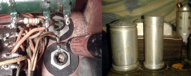 |
|
|
Return to top of page · Post #: 7 · Written at 9:54:02 AM on 10 August 2015.
|
|
|
|
Location: Wangaratta, VIC
Member since 21 February 2009 Member #: 438 Postcount: 5715 |
|
As it is back biased, it is common for the first cap to be hooked to the floating centre tap. As the cap across the backbias is also connected to to the CT, it would be quite logical for both to be in the same can and essential that their negatives do not contact the chassis. |
|
|
Return to top of page · Post #: 8 · Written at 10:35:51 AM on 10 August 2015.
|
|
|
|
Location: Melbourne, VIC
Member since 25 January 2015 Member #: 1686 Postcount: 30 |
|
Thanks Marcc for your reply, |
|
|
Return to top of page · Post #: 9 · Written at 12:41:38 PM on 10 August 2015.
|
|
|
|
Location: Melbourne, VIC
Member since 20 September 2011 Member #: 1009 Postcount: 1263 |
|
The model number should also be stencilled somewhere on the chassis. Stromberg Carlson receivers of that era usually incorporate the model designation with the serial number. |
|
|
Return to top of page · Post #: 10 · Written at 2:01:41 PM on 10 August 2015.
|
|
|
|
Location: Melbourne, VIC
Member since 25 January 2015 Member #: 1686 Postcount: 30 |
|
Hi MonochromeTV, |
|
|
Return to top of page · Post #: 11 · Written at 2:56:20 PM on 10 August 2015.
|
|
|
|
Location: Melbourne, VIC
Member since 20 September 2011 Member #: 1009 Postcount: 1263 |
|
Model 537 & Serial No. 57497. |
|
|
Return to top of page · Post #: 12 · Written at 3:32:29 PM on 10 August 2015.
|
|
|
|
Location: Melbourne, VIC
Member since 25 January 2015 Member #: 1686 Postcount: 30 |
|
Thanks for that information,its much appreciate,will give me an idea what to work on. Back to the library. |
|
|
Return to top of page · Post #: 13 · Written at 3:50:06 PM on 10 August 2015.
|
|
|
|
Location: Wangaratta, VIC
Member since 21 February 2009 Member #: 438 Postcount: 5715 |
|
In the socket of the eye tube is normally a 1M resistor, the attrition rate with those is around 99.9% out of spec. |
|
|
Return to top of page · Post #: 14 · Written at 3:53:01 PM on 10 August 2015.
|
|
|
|
Location: Melbourne, VIC
Member since 25 January 2015 Member #: 1686 Postcount: 30 |
|
Thanks Marc, will check that out also. |
|
|
Return to top of page · Post #: 15 · Written at 4:49:30 PM on 2 September 2015.
|
|
|
|
Location: Melbourne, VIC
Member since 25 January 2015 Member #: 1686 Postcount: 30 |
|
Just wanted to say Thanks,Marcc,MonochromeTV,GTC, for your help and advice,Got the Stromberg/Carlson model 537 up and running,Magic eye working,Sounding Great.Thanks again, Joerik |
|
|
You need to be a member to post comments on this forum.
|
|
Sign In
Vintage Radio and Television is proudly brought to you by an era where things were built with pride and made to last.
DISCLAIMER: Valve radios and televisions contain voltages that can deliver lethal shocks. You should not attempt to work on a valve radio or other electrical appliances unless you know exactly what you are doing and have gained some experience with electronics and working around high voltages. The owner, administrators and staff of Vintage Radio & Television will accept no liability for any damage, injury or loss of life that comes as a result of your use or mis-use of information on this website. Please read our Safety Warning before using this website.
WARNING: Under no circumstances should you ever apply power to a vintage radio, television or other electrical appliance you have acquired without first having it checked and serviced by an experienced person. Also, at no time should any appliance be connected to an electricity supply if the power cord is damaged. If in doubt, do not apply power.
Shintara - Keepin' It Real · VileSilencer - Maintain The Rage