
Tech Talk
Forum home - Go back to Tech talk
|
HMV 471
|
|
|
« Back ·
1 ·
Next »
|
|
|
Return to top of page · Post #: 1 · Written at 2:10:00 PM on 20 May 2015.
|
|
|
|
Location: Tauranga, NZ
Member since 13 July 2010 Member #: 695 Postcount: 35 |
|
This large table top radio was an export model to Aust. and NZ 1936/7. I have a circuit only. Would appreciate any tech. and align info if anyone has. Valves; 80 42 6D6 (2) 6A7 6B7. |
|
|
Return to top of page · Post #: 2 · Written at 10:38:14 PM on 20 May 2015.
|
|

|
Location: Wangaratta, VIC
Member since 21 February 2009 Member #: 438 Postcount: 5703 |
|
Would be interesting to see the circuit to detirmine if it has AGC / AVC, With those valves it is likely. |
|
|
Return to top of page · Post #: 3 · Written at 11:41:10 AM on 21 May 2015.
|
|
|
|
Location: Tauranga, NZ
Member since 13 July 2010 Member #: 695 Postcount: 35 |
|
Have forwarded some photos and circuit for your comments. 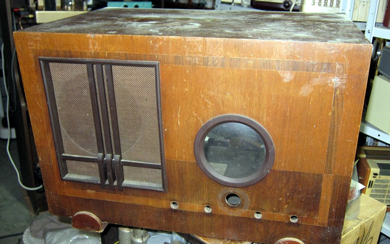 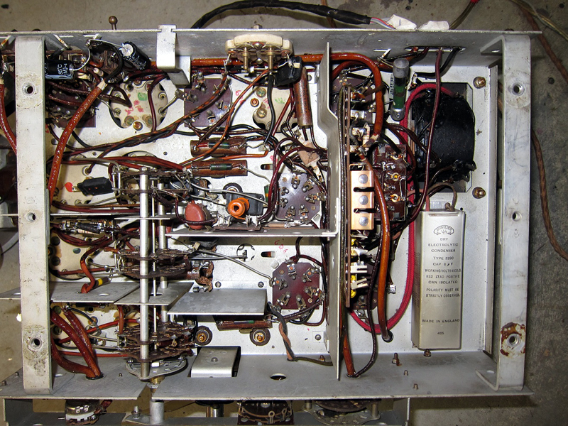 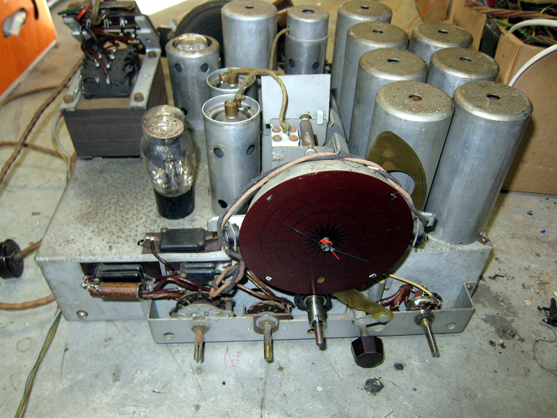  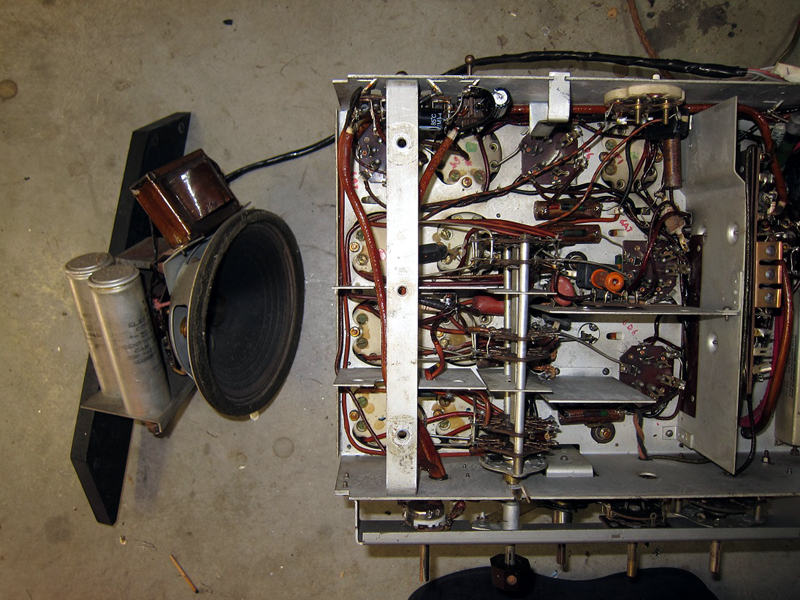 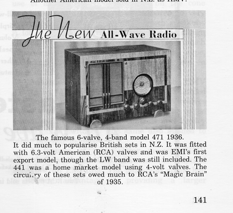 |
|
|
Return to top of page · Post #: 4 · Written at 11:01:54 PM on 21 May 2015.
|
|
|
|
Location: Wangaratta, VIC
Member since 21 February 2009 Member #: 438 Postcount: 5703 |
|
At the time of writing no circuit. The photos show paper caps and they need to be rid of, providing that you have not re-stuffed the old jacket with a new one? |
|
|
Return to top of page · Post #: 5 · Written at 12:01:55 AM on 22 May 2015.
|
|

|
Location: Melbourne, VIC
Member since 20 September 2011 Member #: 1009 Postcount: 1262 |
|
The Australian version of the 471 is the 718. Same cabinet, same valve line-up, but minus the long-wave band. |
|
|
Return to top of page · Post #: 6 · Written at 8:46:00 AM on 22 May 2015.
|
|
|
|
Location: Tauranga, NZ
Member since 13 July 2010 Member #: 695 Postcount: 35 |
|
Thanks Marc and Monochrome. All paper and electro's have been re-stuffed or replaced. A few resistors too far out also. One side of 6.3 volt winding is earthed. The set is working but lacks sensitivity as yet. I wanted to see what the IF frequency was before proceeding further. |
|
|
Return to top of page · Post #: 7 · Written at 9:18:48 AM on 22 May 2015.
|
|
|
|
Location: Wangaratta, VIC
Member since 21 February 2009 Member #: 438 Postcount: 5703 |
|
I would expect that after the mid thirties the IF's would have standardised around 455kHz albeit that HMV did go to an odd frequency. That did make sense as the idea was to to not have a Hetrodyne on the frequency of a radio station. |
|
|
Return to top of page · Post #: 8 · Written at 7:14:03 PM on 22 May 2015.
|
|
|
|
Location: Tauranga, NZ
Member since 13 July 2010 Member #: 695 Postcount: 35 |
|
I have sent the circuit diagram but it hasn't appeared yet. as far as calibration goes. I have sig.generators from Heathkit, Avo, Hickok and Windsor 66 a which I use most. critical frequencies have been checked with a frequency counter. |
|
|
Return to top of page · Post #: 9 · Written at 10:27:53 PM on 22 May 2015.
|
|
|
|
Location: Wangaratta, VIC
Member since 21 February 2009 Member #: 438 Postcount: 5703 |
|
The critical thing when doing an IF alignment, is to not cram too much signal into the Pentagrid. You only need around 40uV. Too much signal will activate the AGC and then you will never get it right. Always use a series cap between generator & Pentagrid (6A7 Top Cap). |
|
|
Return to top of page · Post #: 10 · Written at 7:40:24 PM on 24 May 2015.
|
|

|
Administrator
Location: Naremburn, NSW
Member since 15 November 2005 Member #: 1 Postcount: 7615 |
|
Circuit diagram uploaded. ‾‾‾‾‾‾‾‾‾‾‾‾‾‾‾‾‾‾‾‾‾‾‾‾‾‾‾‾‾‾‾‾‾‾‾‾‾‾‾‾‾‾‾‾‾‾‾‾‾‾‾‾‾‾‾‾‾‾‾‾‾‾‾‾‾‾‾‾ A valve a day keeps the transistor away... |
|
|
« Back ·
1 ·
Next »
|
|
|
You need to be a member to post comments on this forum.
|
|
Sign In
Vintage Radio and Television is proudly brought to you by an era where things were built with pride and made to last.
DISCLAIMER: Valve radios and televisions contain voltages that can deliver lethal shocks. You should not attempt to work on a valve radio or other electrical appliances unless you know exactly what you are doing and have gained some experience with electronics and working around high voltages. The owner, administrators and staff of Vintage Radio & Television will accept no liability for any damage, injury or loss of life that comes as a result of your use or mis-use of information on this website. Please read our Safety Warning before using this website.
WARNING: Under no circumstances should you ever apply power to a vintage radio, television or other electrical appliance you have acquired without first having it checked and serviced by an experienced person. Also, at no time should any appliance be connected to an electricity supply if the power cord is damaged. If in doubt, do not apply power.
Shintara - Keepin' It Real · VileSilencer - Maintain The Rage