
Tech Talk
Forum home - Go back to Tech talk
|
Dominion Radio Tallboy 5V Cables help
|
|
|
Return to top of page · Post #: 1 · Written at 6:25:07 PM on 5 May 2015.
|
|
|
|
Location: Wellington, NZ
Member since 5 May 2015 Member #: 1742 Postcount: 5 |
|
Hi All, |
|
|
Return to top of page · Post #: 2 · Written at 8:49:55 PM on 5 May 2015.
|
|

|
Location: Sydney, NSW
Member since 28 January 2011 Member #: 823 Postcount: 6949 |
|
I have a feeling that it is RCA cables that have been cut at some point. |
|
|
Return to top of page · Post #: 3 · Written at 5:47:56 PM on 6 May 2015.
|
|
|
|
Location: Wellington, NZ
Member since 5 May 2015 Member #: 1742 Postcount: 5 |
|
Thanks for the reply, I have sent some photo's in, hopefully they will be up shortly. 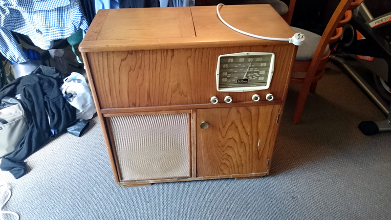 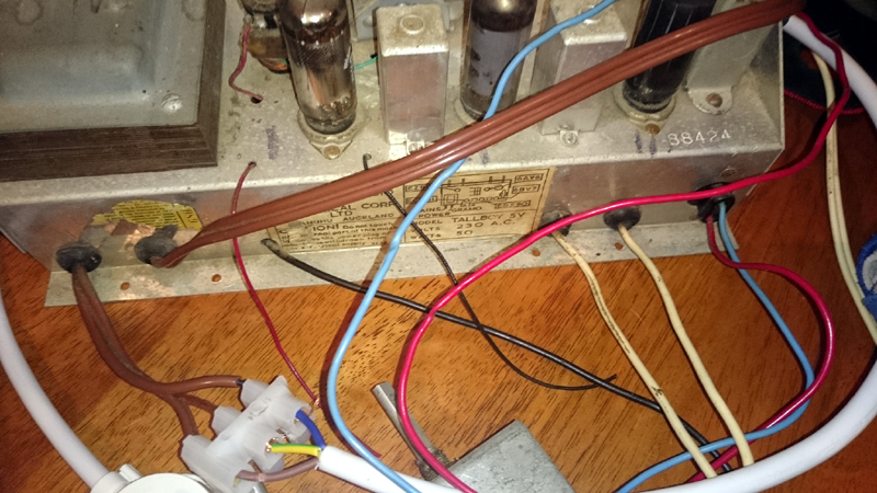 I am not sure if the picture is clear on the front, but the controls are on/off(tone), Volume, radio/gram switch, and tuning. So with that on the front the only inputs seem to be radio and the record player, so maybe not Aux in, potentially aux out? There seems to be a separate bank of valves that have the input cables from the turntable going to them. Currently its in pieces as I am restoring the cabinet, all going back together in the next couple of days hopefully. Thanks for the help. |
|
|
Return to top of page · Post #: 4 · Written at 6:39:53 PM on 6 May 2015.
|
|
|
|
Location: Sydney, NSW
Member since 28 January 2011 Member #: 823 Postcount: 6949 |
|
There seems to be a separate bank of valves that have the input cables from the turntable going to them. |
|
|
Return to top of page · Post #: 5 · Written at 7:20:25 PM on 6 May 2015.
|
|

|
Administrator
Location: Naremburn, NSW
Member since 15 November 2005 Member #: 1 Postcount: 7624 |
|
Photos uploaded. ‾‾‾‾‾‾‾‾‾‾‾‾‾‾‾‾‾‾‾‾‾‾‾‾‾‾‾‾‾‾‾‾‾‾‾‾‾‾‾‾‾‾‾‾‾‾‾‾‾‾‾‾‾‾‾‾‾‾‾‾‾‾‾‾‾‾‾‾ A valve a day keeps the transistor away... |
|
|
Return to top of page · Post #: 6 · Written at 10:25:41 PM on 6 May 2015.
|
|
|
|
Location: Sydney, NSW
Member since 28 January 2011 Member #: 823 Postcount: 6949 |
|
Hard to say from the photo, other than they appear to be exiting the chassis on the output side and the grommets appear to be the same as the others so it may may be original wiring. |
|
|
Return to top of page · Post #: 7 · Written at 10:50:37 PM on 6 May 2015.
|
|
|
|
Administrator
Location: Naremburn, NSW
Member since 15 November 2005 Member #: 1 Postcount: 7624 |
|
All the wiring bar the white flex appears original. Three core 'figure 8' cable was more common in the 1960s. I've seen it on a few radios of the time. As mentioned the picture doesn't show the full story but I am guessing one of the brown three core cables is power in and the other is power out to the turntable. ‾‾‾‾‾‾‾‾‾‾‾‾‾‾‾‾‾‾‾‾‾‾‾‾‾‾‾‾‾‾‾‾‾‾‾‾‾‾‾‾‾‾‾‾‾‾‾‾‾‾‾‾‾‾‾‾‾‾‾‾‾‾‾‾‾‾‾‾ A valve a day keeps the transistor away... |
|
|
Return to top of page · Post #: 8 · Written at 8:06:03 PM on 8 May 2015.
|
|
|
|
Location: Wellington, NZ
Member since 5 May 2015 Member #: 1742 Postcount: 5 |
|
Have sent some photos in of the underneath of the chassis and the valves. Hopefully that will help us shed some light on what the cables are. Is there a sensible way to test them? 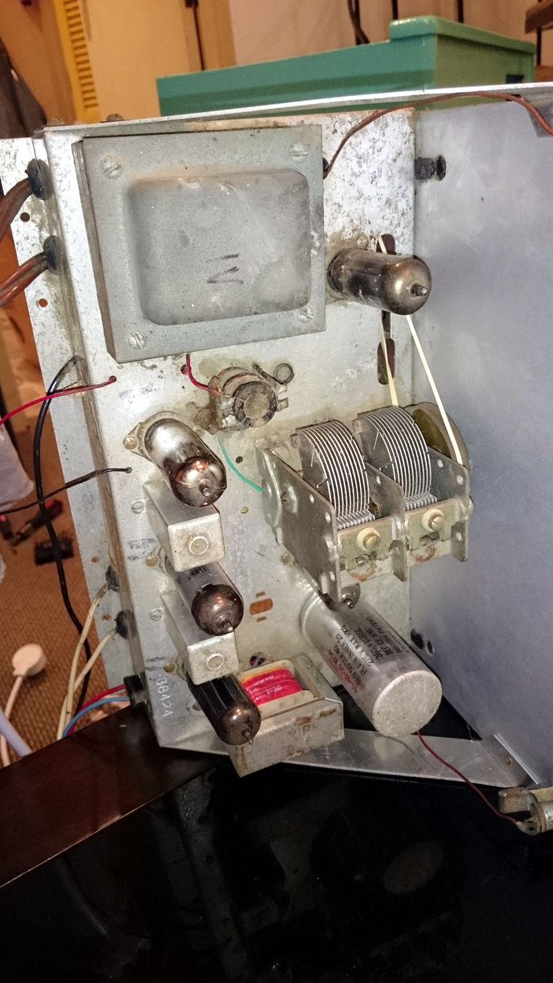 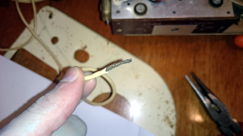 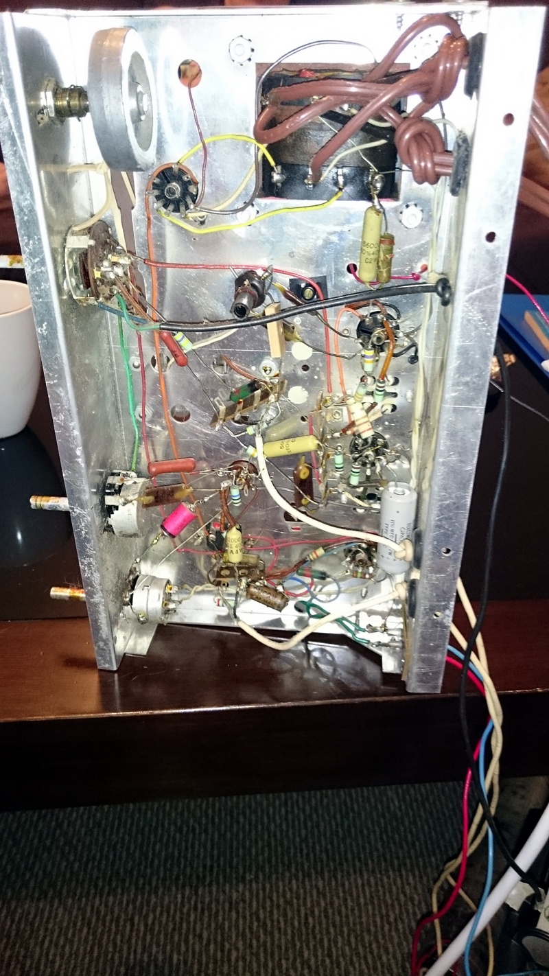 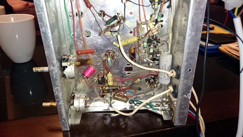 |
|
|
Return to top of page · Post #: 9 · Written at 8:20:38 PM on 8 May 2015.
|
|
|
|
Location: Sydney, NSW
Member since 28 January 2011 Member #: 823 Postcount: 6949 |
|
Valves can be tested to some extent in a valve tester, but the true test of a valve is how it performs in the equipment itself. |
|
|
Return to top of page · Post #: 10 · Written at 8:56:04 AM on 9 May 2015.
|
|
|
|
Administrator
Location: Naremburn, NSW
Member since 15 November 2005 Member #: 1 Postcount: 7624 |
|
Your avatar image displays as a black square on my monitor. Is that your intention? ‾‾‾‾‾‾‾‾‾‾‾‾‾‾‾‾‾‾‾‾‾‾‾‾‾‾‾‾‾‾‾‾‾‾‾‾‾‾‾‾‾‾‾‾‾‾‾‾‾‾‾‾‾‾‾‾‾‾‾‾‾‾‾‾‾‾‾‾ A valve a day keeps the transistor away... |
|
|
Return to top of page · Post #: 11 · Written at 11:10:09 PM on 9 May 2015.
|
|
|
|
Location: Australia, SA
Member since 21 December 2011 Member #: 1047 Postcount: 85 |
|
One white cable would be for the phono pickup and the other could be for a microphone. I have a Kriesler from the 60's that came with a microphone. |
|
|
Return to top of page · Post #: 12 · Written at 11:40:39 PM on 9 May 2015.
|
|
|
|
Location: Sydney, NSW
Member since 28 January 2011 Member #: 823 Postcount: 6949 |
|
As per the thread title and the chassis sticker in the second photo of post #3, it's a Dominion Radio Tallboy 5V. (Dominion Radio & Electrical Corp.) |
|
|
Return to top of page · Post #: 13 · Written at 11:35:45 PM on 22 July 2017.
|
|
|
|
Location: Christchurch, NZ
Member since 20 January 2017 Member #: 2046 Postcount: 1 |
|
Hi Nickw, I believe I can help you, I have the exact same radiogram in mint condition, a LaGloria 1060S, will post pics & valve lineup etc... soon. The amphenol coaxial connecter under the record player is for a mic. 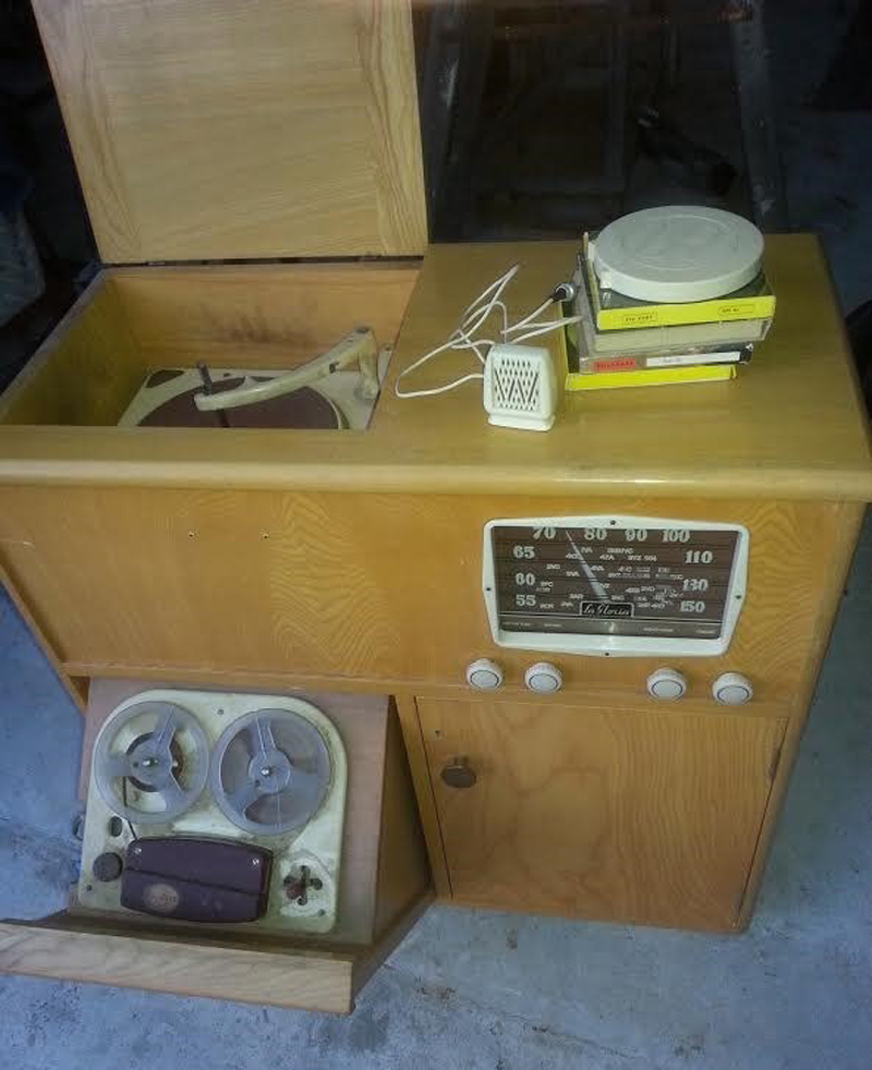 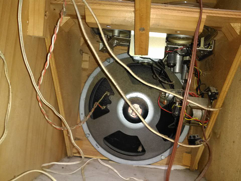 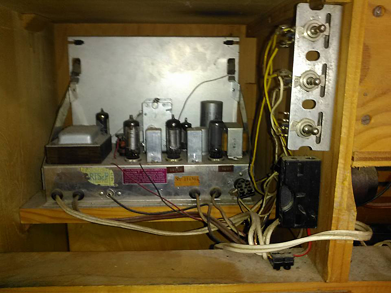 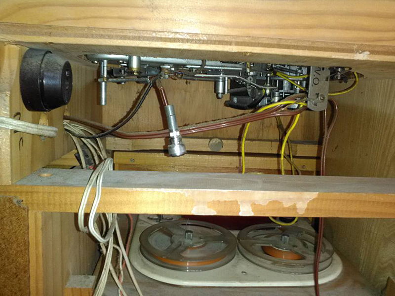 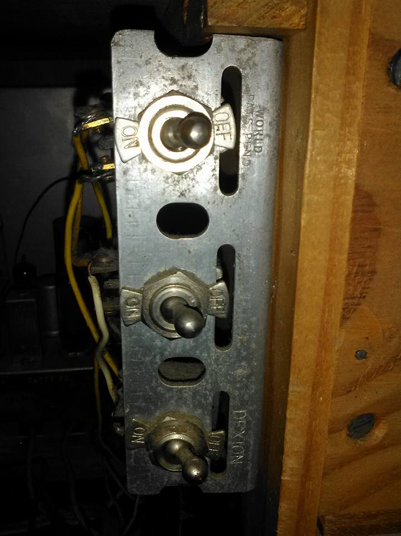 |
|
|
Return to top of page · Post #: 14 · Written at 11:53:21 PM on 22 July 2017.
|
|

|
Location: Wangaratta, VIC
Member since 21 February 2009 Member #: 438 Postcount: 5715 |
|
The photo shows "wax paper" caps, if they are still in there, they should be replaced. |
|
|
Return to top of page · Post #: 15 · Written at 2:55:57 PM on 5 August 2017.
|
|
|
|
Administrator
Location: Naremburn, NSW
Member since 15 November 2005 Member #: 1 Postcount: 7624 |
|
Photos uploaded to Post 13. ‾‾‾‾‾‾‾‾‾‾‾‾‾‾‾‾‾‾‾‾‾‾‾‾‾‾‾‾‾‾‾‾‾‾‾‾‾‾‾‾‾‾‾‾‾‾‾‾‾‾‾‾‾‾‾‾‾‾‾‾‾‾‾‾‾‾‾‾ A valve a day keeps the transistor away... |
|
|
You need to be a member to post comments on this forum.
|
|

 NickW: per my earlier request (post #6), let us know the valve types listed on that sticker, please.
Sign In
Vintage Radio and Television is proudly brought to you by an era where things were built with pride and made to last.
DISCLAIMER: Valve radios and televisions contain voltages that can deliver lethal shocks. You should not attempt to work on a valve radio or other electrical appliances unless you know exactly what you are doing and have gained some experience with electronics and working around high voltages. The owner, administrators and staff of Vintage Radio & Television will accept no liability for any damage, injury or loss of life that comes as a result of your use or mis-use of information on this website. Please read our Safety Warning before using this website.
WARNING: Under no circumstances should you ever apply power to a vintage radio, television or other electrical appliance you have acquired without first having it checked and serviced by an experienced person. Also, at no time should any appliance be connected to an electricity supply if the power cord is damaged. If in doubt, do not apply power.
Shintara - Keepin' It Real · VileSilencer - Maintain The Rage