Tech Talk
Forum home - Go back to Tech talk
|
Phillips 123 Restoration
|
|
|
Return to top of page · Post #: 1 · Written at 3:00:58 AM on 29 March 2015.
|
|
|
|
Location: Devonport, TAS
Member since 26 March 2015 Member #: 1718 Postcount: 22 |
|
I just finished the circuit work on a Philips 123 and had some questions. |
|
|
Return to top of page · Post #: 2 · Written at 8:56:56 AM on 29 March 2015.
|
|
|
|
Location: Wangaratta, VIC
Member since 21 February 2009 Member #: 438 Postcount: 5671 |
|
I see not enough detail on what you have not done............... |
|
|
Return to top of page · Post #: 3 · Written at 12:26:10 PM on 29 March 2015.
|
|
|
|
Location: Devonport, TAS
Member since 26 March 2015 Member #: 1718 Postcount: 22 |
|
Ah thanks very much. Caps and many resistors were replaced. I have noticed it has improved some after running for some time. Still probably not optimal though. |
|
|
Return to top of page · Post #: 4 · Written at 1:59:57 PM on 29 March 2015.
|
|
|
|
Location: Tamworth, NSW
Member since 6 April 2012 Member #: 1126 Postcount: 472 |
|
CRO probably doesn't matter what you use. As long as you have confidence in the unit. Bear in mind a 60 year old CRO will have the same issues as a 60 year old radio with caps and resistors. My CRO is around 20yr old. I also have an older 1966 era CRO with 16 valves, it weighs a tonne, full of wax caps and is very unreliable. Its currently in bits and is likely to stay that way for some time. |
|
|
Return to top of page · Post #: 5 · Written at 4:58:55 PM on 29 March 2015.
|
|
|
|
Location: Devonport, TAS
Member since 26 March 2015 Member #: 1718 Postcount: 22 |
|
16 Valves! Hardcore |
|
|
Return to top of page · Post #: 6 · Written at 9:25:41 PM on 29 March 2015.
|
|
|
|
Location: Wangaratta, VIC
Member since 21 February 2009 Member #: 438 Postcount: 5671 |
|
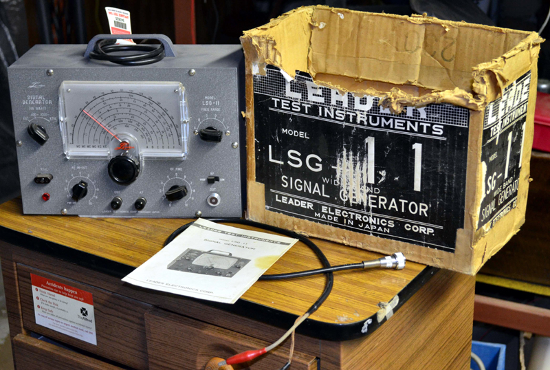
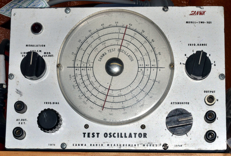
I do tend to salvage a bit of the old test stuff, I am waiting on some Plexiglas to repair the window in a US Philco, BC221-N frequency meter. I have replaced dodgy caps & resistors that just had to go so it will be interesting to see if it stays in calibration with its book?   Both of these units were basically bought in to save them from scrap, but I did evaluate them to see if they were worth overhauling. I repainted the LSG These are surplus to requirements. I will send photo's to Brad with more info. One CRO here is a Heathkit OS-1 that seems to need another new set of filter caps. A dual trace BWD 539C I bought at a clearing sale & took over 2 Hrs just to clean and a Jaycar QC1910. Marc |
|
|
Return to top of page · Post #: 7 · Written at 12:55:49 PM on 3 April 2015.
|
|
|
|
Location: Canberra, ACT
Member since 23 August 2012 Member #: 1208 Postcount: 587 |
|
I had a lot of volume issues restoring my Philips 123. It's a complicated circuit - and was my first valve unit restoration - so I had a lot to learn. |
|
|
Return to top of page · Post #: 8 · Written at 10:49:19 AM on 4 April 2015.
|
|
|
|
Location: Wangaratta, VIC
Member since 21 February 2009 Member #: 438 Postcount: 5671 |
|
That's a fairly common arrangement , but the pots are scarce. Astor & many others did that feedback trick. There is a guy in America called Mark Oppat (not sure of spelling) who rebuilds pots. |
|
|
Return to top of page · Post #: 9 · Written at 9:36:27 PM on 4 April 2015.
|
|
|
|
Location: Adelaide, SA
Member since 27 February 2010 Member #: 630 Postcount: 398 |
|
Hi ‾‾‾‾‾‾‾‾‾‾‾‾‾‾‾‾‾‾‾‾‾‾‾‾‾‾‾‾‾‾‾‾‾‾‾‾‾‾‾‾‾‾‾‾‾‾‾‾‾‾‾‾‾‾‾‾‾‾‾‾‾‾‾‾‾‾‾‾ Valve radios, They just don't make them like they used to |
|
|
Return to top of page · Post #: 10 · Written at 9:47:05 PM on 4 April 2015.
|
|
|
|
Location: Wangaratta, VIC
Member since 21 February 2009 Member #: 438 Postcount: 5671 |
|
Take a careful look at the transformer, 132L & a few others with a similar construction have a bad habit of letting the windings out of the side. |
|
|
Return to top of page · Post #: 11 · Written at 6:35:54 PM on 14 April 2015.
|
|
|
|
Location: Golden Grove, SA
Member since 10 April 2015 Member #: 1726 Postcount: 149 |
|
The Transformer is definitely worth checking, as my 132 the windings are out the side. |
|
|
Return to top of page · Post #: 12 · Written at 6:28:20 PM on 22 April 2015.
|
|
|
|
Location: Adelaide, SA
Member since 27 February 2010 Member #: 630 Postcount: 398 |
|
Hi "TheDanger" ‾‾‾‾‾‾‾‾‾‾‾‾‾‾‾‾‾‾‾‾‾‾‾‾‾‾‾‾‾‾‾‾‾‾‾‾‾‾‾‾‾‾‾‾‾‾‾‾‾‾‾‾‾‾‾‾‾‾‾‾‾‾‾‾‾‾‾‾ Valve radios, They just don't make them like they used to |
|
|
Return to top of page · Post #: 13 · Written at 12:28:04 AM on 6 May 2015.
|
|
|
|
Location: Devonport, TAS
Member since 26 March 2015 Member #: 1718 Postcount: 22 |
|
Hi Dan |
|
|
Return to top of page · Post #: 14 · Written at 2:50:52 PM on 6 May 2015.
|
|
|
|
Location: Adelaide, SA
Member since 27 February 2010 Member #: 630 Postcount: 398 |
|
Hi ‾‾‾‾‾‾‾‾‾‾‾‾‾‾‾‾‾‾‾‾‾‾‾‾‾‾‾‾‾‾‾‾‾‾‾‾‾‾‾‾‾‾‾‾‾‾‾‾‾‾‾‾‾‾‾‾‾‾‾‾‾‾‾‾‾‾‾‾ Valve radios, They just don't make them like they used to |
|
|
Return to top of page · Post #: 15 · Written at 4:18:48 PM on 6 May 2015.
|
|
|
|
Location: Devonport, TAS
Member since 26 March 2015 Member #: 1718 Postcount: 22 |
|
I'm using this one as my main listener at the moment. Really have to get started on some sort of transmitter sometime. I pick up only one station on AM where I am and lets just say its a pretty boring one. |
|
|
You need to be a member to post comments on this forum.
|
|

Sign In

Vintage Radio and Television is proudly brought to you by an era where things were built with pride and made to last.
DISCLAIMER: Valve radios and televisions contain voltages that can deliver lethal shocks. You should not attempt to work on a valve radio or other electrical appliances unless you know exactly what you are doing and have gained some experience with electronics and working around high voltages. The owner, administrators and staff of Vintage Radio & Television will accept no liability for any damage, injury or loss of life that comes as a result of your use or mis-use of information on this website. Please read our Safety Warning before using this website.
WARNING: Under no circumstances should you ever apply power to a vintage radio, television or other electrical appliance you have acquired without first having it checked and serviced by an experienced person. Also, at no time should any appliance be connected to an electricity supply if the power cord is damaged. If in doubt, do not apply power.
Shintara - Keepin' It Real · VileSilencer - Maintain The Rage
