
Tech Talk
Forum home - Go back to Tech talk
|
Composite mod for Pye 12G15B 12"
|
|
|
« Back ·
1 ·
Next »
|
|
|
Return to top of page · Post #: 1 · Written at 3:53:57 PM on 25 February 2015.
|
|
|
|
Location: Horsham, VIC
Member since 19 December 2013 Member #: 1468 Postcount: 33 |
|
Hi Guy's it's been a while. |
|
|
Return to top of page · Post #: 2 · Written at 7:51:24 PM on 27 February 2015.
|
|
|
|
Location: Ballarat, VIC
Member since 4 January 2011 Member #: 803 Postcount: 456 |
|
Your in luck, I have the schematic for the 12G15B. It uses a Japanese chassis (probably Sharp) not an Australian Pye chassis so I wasn't sure if I had it. Give me a day or two and I'll scan the circuit and try and talk you through what you need to do to mod yours for video input. |
|
|
Return to top of page · Post #: 3 · Written at 8:20:30 PM on 27 February 2015.
|
|
|
|
Location: Horsham, VIC
Member since 19 December 2013 Member #: 1468 Postcount: 33 |
|
Fantastic, What a champ! |
|
|
Return to top of page · Post #: 4 · Written at 7:57:46 PM on 1 March 2015.
|
|
|
|
Location: Ballarat, VIC
Member since 4 January 2011 Member #: 803 Postcount: 456 |
|
This should be a fairly easy conversion. The TV has a grounded chassis so it will be safe to work on. I thought it may have been a Sharp chassis but it's actually Korean I think, as it uses KS series transistors. |
|
|
Return to top of page · Post #: 5 · Written at 7:22:10 PM on 2 March 2015.
|
|
|
|
Location: Horsham, VIC
Member since 19 December 2013 Member #: 1468 Postcount: 33 |
|
Thanks for that, I'll get stuck into the mod in a day or two. Thanks for the time taken to do the mod. |
|
|
Return to top of page · Post #: 6 · Written at 9:12:28 PM on 2 March 2015.
|
|
|
|
Location: Ballarat, VIC
Member since 4 January 2011 Member #: 803 Postcount: 456 |
|
Glad to help. Good luck with the mod. |
|
|
Return to top of page · Post #: 7 · Written at 12:08:13 PM on 8 March 2015.
|
|
|
|
Location: Horsham, VIC
Member since 19 December 2013 Member #: 1468 Postcount: 33 |
|
TV collector, thanks so much for the mod, It works. The only issue I had was de-soldering the L103 leg as it was located in a shield box & I had to disassemble half the TV to get to it. Anyway here are a couple of photo's to show the result. Since taking the photo's I've re-done the job with some shielded cable & ordered a 5 pin din plug for the computer composite input. 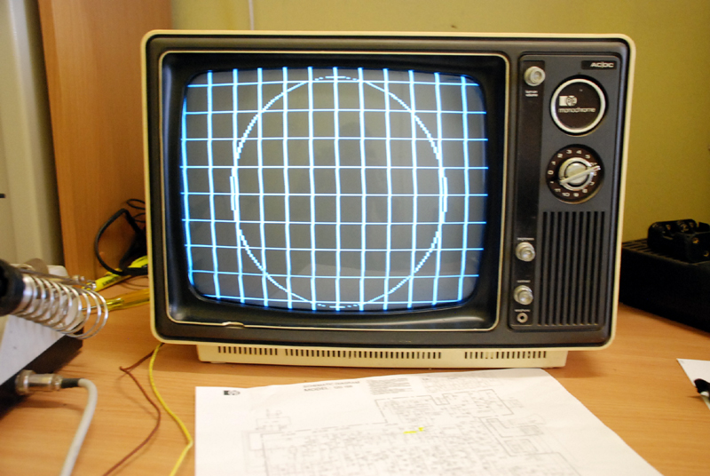 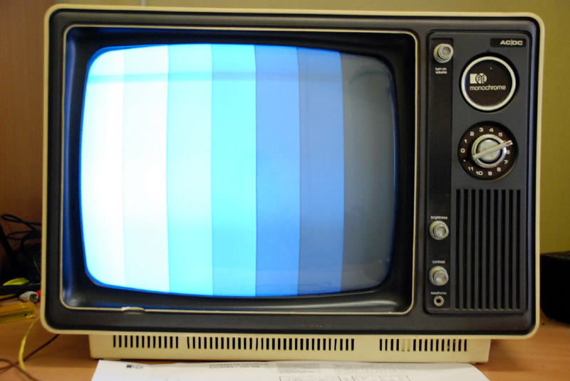 Thanks so much for your help. Doug. |
|
|
Return to top of page · Post #: 8 · Written at 9:57:08 PM on 9 March 2015.
|
|
|
|
Location: Ballarat, VIC
Member since 4 January 2011 Member #: 803 Postcount: 456 |
|
Looking good, I'm glad it worked out. |
|
|
« Back ·
1 ·
Next »
|
|
|
You need to be a member to post comments on this forum.
|
|
Sign In
Vintage Radio and Television is proudly brought to you by an era where things were built with pride and made to last.
DISCLAIMER: Valve radios and televisions contain voltages that can deliver lethal shocks. You should not attempt to work on a valve radio or other electrical appliances unless you know exactly what you are doing and have gained some experience with electronics and working around high voltages. The owner, administrators and staff of Vintage Radio & Television will accept no liability for any damage, injury or loss of life that comes as a result of your use or mis-use of information on this website. Please read our Safety Warning before using this website.
WARNING: Under no circumstances should you ever apply power to a vintage radio, television or other electrical appliance you have acquired without first having it checked and serviced by an experienced person. Also, at no time should any appliance be connected to an electricity supply if the power cord is damaged. If in doubt, do not apply power.
Shintara - Keepin' It Real · VileSilencer - Maintain The Rage