
Tech Talk
Forum home - Go back to Tech talk
|
Frequency Doubler
|
|
|
« Back ·
1 ·
Next »
|
|
|
Return to top of page · Post #: 1 · Written at 7:21:06 PM on 7 November 2014.
|
|
|
|
Location: Somewhere, USA
Member since 22 October 2013 Member #: 1437 Postcount: 896 |
|
Hi Guys, I want to double an AC/RF 10 MHz frequency of low voltage (about 1 Volt) on a coax line. |
|
|
Return to top of page · Post #: 2 · Written at 11:16:09 PM on 7 November 2014.
|
|

|
Location: Wangaratta, VIC
Member since 21 February 2009 Member #: 438 Postcount: 5720 |
|
Not sure where this is going but one tends to use "clocking" using a nand gate, or multi-vibrator where you can set them to divide, or when triggered give two pulses when one is applied etc. |
|
|
Return to top of page · Post #: 3 · Written at 11:31:52 PM on 7 November 2014.
|
|
|
|
Location: Somewhere, USA
Member since 22 October 2013 Member #: 1437 Postcount: 896 |
|
Hi Marcc, |
|
|
Return to top of page · Post #: 4 · Written at 12:25:47 AM on 8 November 2014.
|
|

|
Administrator
Location: Naremburn, NSW
Member since 15 November 2005 Member #: 1 Postcount: 7633 |
|
Quite correct. Logic is just 0's and 1's. The gates on a 4000-series IC (or equivalent) will go high or remain low depending on the state of the inputs. Generating a sine wave will require more elaborate circuitry, especially since you will need to go into the negative for half the cycle. ‾‾‾‾‾‾‾‾‾‾‾‾‾‾‾‾‾‾‾‾‾‾‾‾‾‾‾‾‾‾‾‾‾‾‾‾‾‾‾‾‾‾‾‾‾‾‾‾‾‾‾‾‾‾‾‾‾‾‾‾‾‾‾‾‾‾‾‾ A valve a day keeps the transistor away... |
|
|
Return to top of page · Post #: 5 · Written at 9:51:18 AM on 8 November 2014.
|
|
|
|
Location: Wangaratta, VIC
Member since 21 February 2009 Member #: 438 Postcount: 5720 |
|
I have actually made a 455kHz Crystal locked oscillator using three sections of a Quad NAND (I think..still have circuit) That fed a dual gate FET as the (controlable) mixer, the other gate having the audio from a 555. |
|
|
Return to top of page · Post #: 6 · Written at 10:03:05 AM on 8 November 2014.
|
|
|
|
Location: Melbourne, VIC
Member since 5 October 2009 Member #: 555 Postcount: 470 |
|
Hi Art, ‾‾‾‾‾‾‾‾‾‾‾‾‾‾‾‾‾‾‾‾‾‾‾‾‾‾‾‾‾‾‾‾‾‾‾‾‾‾‾‾‾‾‾‾‾‾‾‾‾‾‾‾‾‾‾‾‾‾‾‾‾‾‾‾‾‾‾‾ Cheers, Ian |
|
|
Return to top of page · Post #: 7 · Written at 11:46:39 AM on 8 November 2014.
|
|
|
|
Location: Somewhere, USA
Member since 22 October 2013 Member #: 1437 Postcount: 896 |
|
Yes it's an LC calculator I'm thinking of, but I was kinda hoping for something more focussed on radio |
|
|
Return to top of page · Post #: 8 · Written at 10:17:37 AM on 10 November 2014.
|
|
|
|
Location: Oradell, US
Member since 2 April 2010 Member #: 643 Postcount: 839 |
|
If I wanted to double the frequency of a 10MHz clock (for use with microprocessors, so it'd be something like TTL style signals), assuming the clock is 50% duty cycle, I would run the clock through a delay line of time delay 1/4 of a full clock cycle, then feed the delayed and the undelayed clock into a XOR gate. The gate's output should look like a 20MHz clock. The timing of one 20MHz pulse to the next pulse may be uneven over 2 cycles, but micros don't really much care about that, as long as the time deviation is less than say 10%. |
|
|
Return to top of page · Post #: 9 · Written at 6:14:36 PM on 10 November 2014.
|
|
|
|
Location: Wangaratta, VIC
Member since 21 February 2009 Member #: 438 Postcount: 5720 |
|
With an oscillator generating 2nd harmonics something like a 20MHz version of an IFT is all that is likely required. |
|
|
Return to top of page · Post #: 10 · Written at 7:14:19 PM on 11 November 2014.
|
|
|
|
Location: Somewhere, USA
Member since 22 October 2013 Member #: 1437 Postcount: 896 |
|
Hi Wa2ise, Yes the logic signal is fine for the micro, I have tried both AC and DC PWM at the same frequency with the same results. |
|
|
Return to top of page · Post #: 11 · Written at 6:48:56 PM on 15 December 2014.
|
|
|
|
Location: Somewhere, USA
Member since 22 October 2013 Member #: 1437 Postcount: 896 |
|
So basically a tank circuit resonant at the desired freq is all that's required. |
|
|
Return to top of page · Post #: 12 · Written at 8:59:45 PM on 15 December 2014.
|
|
|
|
Location: Wangaratta, VIC
Member since 21 February 2009 Member #: 438 Postcount: 5720 |
|
Do be careful of what is on the web, there is quite a bit of misinformation out there. |
|
|
Return to top of page · Post #: 13 · Written at 10:24:21 PM on 15 December 2014.
|
|
|
|
Location: Somewhere, USA
Member since 22 October 2013 Member #: 1437 Postcount: 896 |
|
Circuit Girl is very well known.. actually works for Valve software last time I heard, |
|
|
Return to top of page · Post #: 14 · Written at 11:22:58 PM on 16 December 2014.
|
|
|
|
Location: Somewhere, USA
Member since 22 October 2013 Member #: 1437 Postcount: 896 |
|
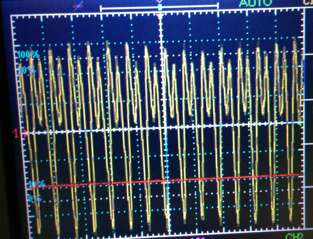
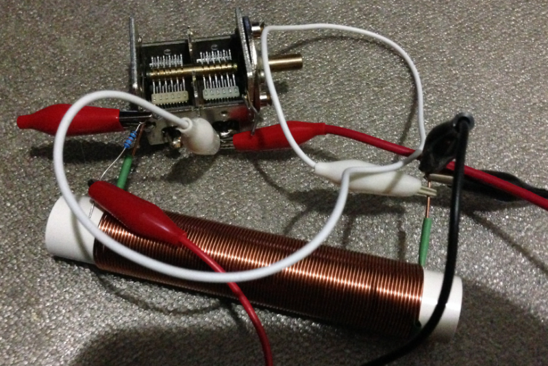
Ok, so to prove to myself, I wound an unknown inductor a while back to tap into later. |
|
|
« Back ·
1 ·
Next »
|
|
|
You need to be a member to post comments on this forum.
|
|


Sign In
Vintage Radio and Television is proudly brought to you by an era where things were built with pride and made to last.
DISCLAIMER: Valve radios and televisions contain voltages that can deliver lethal shocks. You should not attempt to work on a valve radio or other electrical appliances unless you know exactly what you are doing and have gained some experience with electronics and working around high voltages. The owner, administrators and staff of Vintage Radio & Television will accept no liability for any damage, injury or loss of life that comes as a result of your use or mis-use of information on this website. Please read our Safety Warning before using this website.
WARNING: Under no circumstances should you ever apply power to a vintage radio, television or other electrical appliance you have acquired without first having it checked and serviced by an experienced person. Also, at no time should any appliance be connected to an electricity supply if the power cord is damaged. If in doubt, do not apply power.
Shintara - Keepin' It Real · VileSilencer - Maintain The Rage