
Tech Talk
Forum home - Go back to Tech talk
|
Radio ID and some help please
|
|
|
Return to top of page · Post #: 1 · Written at 5:57:30 PM on 20 October 2014.
|
|
|
|
Location: Melbourne, VIC
Member since 20 October 2014 Member #: 1640 Postcount: 19 |
|
G'day Guys, First post here so go easy on me not (-; 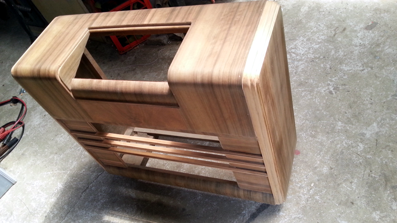 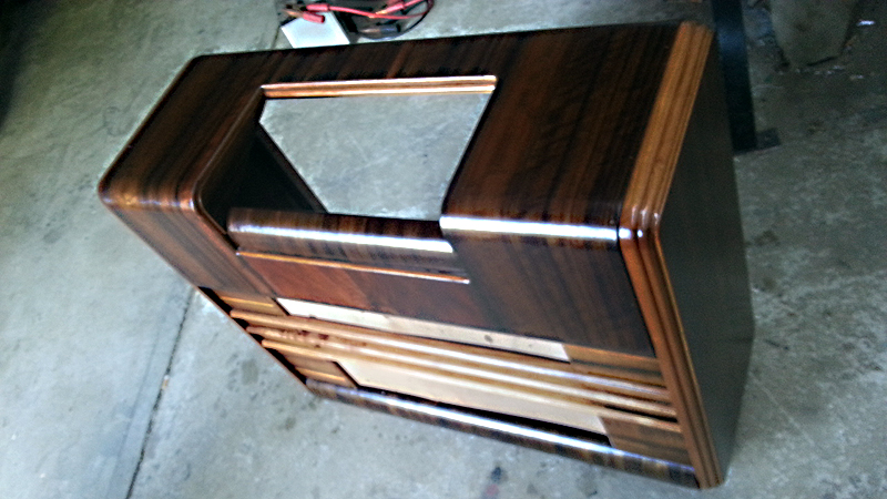 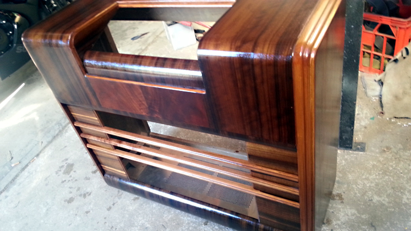 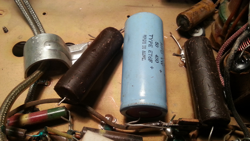 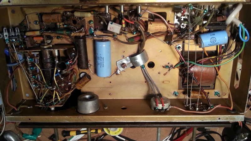 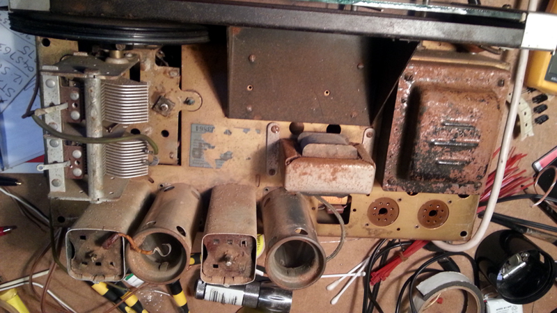 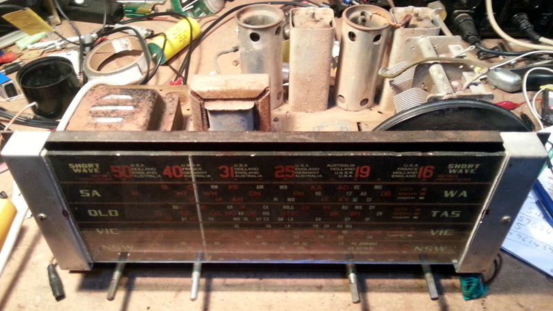 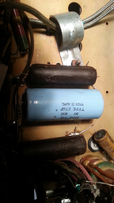 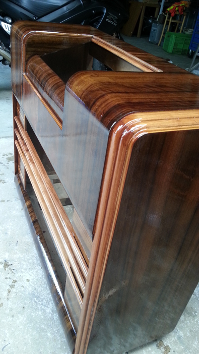 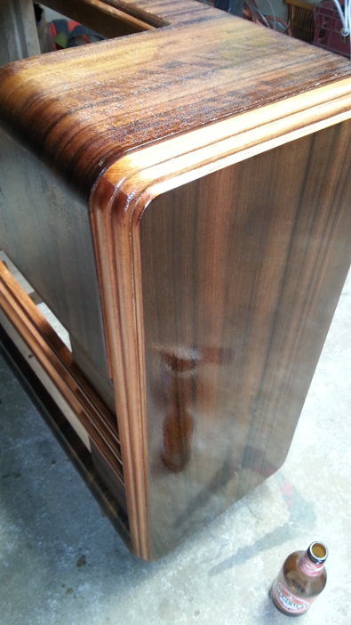 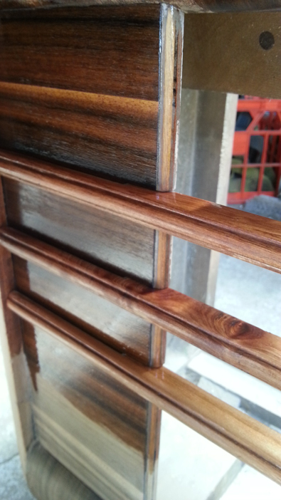 |
|
|
Return to top of page · Post #: 2 · Written at 6:06:18 PM on 20 October 2014.
|
|
|
|
Location: Melbourne, VIC
Member since 20 October 2014 Member #: 1640 Postcount: 19 |
|
Hmm, do you always need to email admin to post pictures? Well I have done that, hopefully they are up soon... |
|
|
Return to top of page · Post #: 3 · Written at 6:51:49 PM on 20 October 2014.
|
|

|
Location: Sydney, NSW
Member since 28 January 2011 Member #: 823 Postcount: 6949 |
|
do you always need to email admin to post pictures? |
|
|
Return to top of page · Post #: 4 · Written at 7:32:04 PM on 20 October 2014.
|
|

|
Administrator
Location: Naremburn, NSW
Member since 15 November 2005 Member #: 1 Postcount: 7624 |
|
G'day Laurie, ‾‾‾‾‾‾‾‾‾‾‾‾‾‾‾‾‾‾‾‾‾‾‾‾‾‾‾‾‾‾‾‾‾‾‾‾‾‾‾‾‾‾‾‾‾‾‾‾‾‾‾‾‾‾‾‾‾‾‾‾‾‾‾‾‾‾‾‾ A valve a day keeps the transistor away... |
|
|
Return to top of page · Post #: 5 · Written at 7:47:07 PM on 20 October 2014.
|
|
|
|
Location: Melbourne, VIC
Member since 20 October 2014 Member #: 1640 Postcount: 19 |
|
No worries, well I shall wait for now, but until then ill fire first question.... |
|
|
Return to top of page · Post #: 6 · Written at 8:41:44 PM on 20 October 2014.
|
|
|
|
Location: Melbourne, VIC
Member since 20 October 2014 Member #: 1640 Postcount: 19 |
|
I've found a picture of the radio I have online anyway, will see if I can post a link....this one isnt mine...see if the link is helpful |
|
|
Return to top of page · Post #: 7 · Written at 8:49:00 PM on 20 October 2014.
|
|
|
|
Location: Melbourne, VIC
Member since 20 October 2014 Member #: 1640 Postcount: 19 |
|
|
|
|
Return to top of page · Post #: 8 · Written at 9:22:37 PM on 20 October 2014.
|
|

|
Location: Melbourne, VIC
Member since 20 September 2011 Member #: 1009 Postcount: 1263 |
|
I think it might be a Kriesler 11-9, which is a console version of a 11-7. |
|
|
Return to top of page · Post #: 9 · Written at 9:35:34 PM on 20 October 2014.
|
|
|
|
Administrator
Location: Naremburn, NSW
Member since 15 November 2005 Member #: 1 Postcount: 7624 |
|
The dial glass suggests Kriesler. They did make some behemoth consoles which performed well. I am not sure of the model number. It could be an 11-7/9, as it was a four valver. ‾‾‾‾‾‾‾‾‾‾‾‾‾‾‾‾‾‾‾‾‾‾‾‾‾‾‾‾‾‾‾‾‾‾‾‾‾‾‾‾‾‾‾‾‾‾‾‾‾‾‾‾‾‾‾‾‾‾‾‾‾‾‾‾‾‾‾‾ A valve a day keeps the transistor away... |
|
|
Return to top of page · Post #: 10 · Written at 9:46:21 AM on 21 October 2014.
|
|
|
|
Location: Melbourne, VIC
Member since 20 October 2014 Member #: 1640 Postcount: 19 |
|
Its definitely a Kriesler...Unfortunately I am missing the cover glass that fits to the cabinet covering dial glass... |
|
|
Return to top of page · Post #: 11 · Written at 9:47:03 AM on 21 October 2014.
|
|
|
|
Location: Melbourne, VIC
Member since 20 October 2014 Member #: 1640 Postcount: 19 |
|
Oh and thanks Brad for the fast upload of pictures...they look great, thankyou. |
|
|
Return to top of page · Post #: 12 · Written at 10:34:00 AM on 21 October 2014.
|
|
|
|
Administrator
Location: Naremburn, NSW
Member since 15 November 2005 Member #: 1 Postcount: 7624 |
|
Has anyone got any ideas on the value of the brown wax coated bullet like caps I've pictured? ‾‾‾‾‾‾‾‾‾‾‾‾‾‾‾‾‾‾‾‾‾‾‾‾‾‾‾‾‾‾‾‾‾‾‾‾‾‾‾‾‾‾‾‾‾‾‾‾‾‾‾‾‾‾‾‾‾‾‾‾‾‾‾‾‾‾‾‾ A valve a day keeps the transistor away... |
|
|
Return to top of page · Post #: 13 · Written at 11:17:54 AM on 21 October 2014.
|
|
|
|
Location: Melbourne, VIC
Member since 20 October 2014 Member #: 1640 Postcount: 19 |
|
Ok I have found a schematic for the 11-7...Crikey these old diagrams are hard to work through...I am still working through it but so far I cannot see anyplace for this 50μF 450v Electrolytic .The big Blue one pictured which has been added by someone...I am thinking these brown wax coated may be 0.1μF 400v, I should mention that there were 3 of these brown capacitors in circuit,2 of in parallel with the 50μF Blue cap, I have removed some before photos |
|
|
Return to top of page · Post #: 14 · Written at 11:27:35 AM on 21 October 2014.
|
|
|
|
Location: Melbourne, VIC
Member since 20 September 2011 Member #: 1009 Postcount: 1263 |
|
Laurie. |
|
|
Return to top of page · Post #: 15 · Written at 12:56:49 PM on 21 October 2014.
|
|
|
|
Location: Melbourne, VIC
Member since 20 October 2014 Member #: 1640 Postcount: 19 |
|
Thanks Monochrome, although I think I am getting somewhere...the diagram definitely indicates those caps are C28 ABC 0.1μF 400v paper caps, Why that Electrolytic is there I have no idea but its coming out! |
|
|
You need to be a member to post comments on this forum.
|
|
Sign In
Vintage Radio and Television is proudly brought to you by an era where things were built with pride and made to last.
DISCLAIMER: Valve radios and televisions contain voltages that can deliver lethal shocks. You should not attempt to work on a valve radio or other electrical appliances unless you know exactly what you are doing and have gained some experience with electronics and working around high voltages. The owner, administrators and staff of Vintage Radio & Television will accept no liability for any damage, injury or loss of life that comes as a result of your use or mis-use of information on this website. Please read our Safety Warning before using this website.
WARNING: Under no circumstances should you ever apply power to a vintage radio, television or other electrical appliance you have acquired without first having it checked and serviced by an experienced person. Also, at no time should any appliance be connected to an electricity supply if the power cord is damaged. If in doubt, do not apply power.
Shintara - Keepin' It Real · VileSilencer - Maintain The Rage